82
03-1491-00-11.fm
Operation
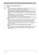
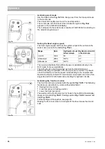
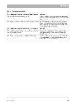
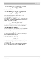
3.6.3
Ballast
Calculating ballast
You require the following data to calculate the total weight, the axle loads
and the tyre load capacity as well as the required minimum ballast:
1) See Citymaster 1600 technical
data.
2) See price list and/or operating
manual of the attachment
3) Dimensioning
•
T
L
(kg) = empty weight of the vehicle (1)
•
T
V
(kg) = front axle load of the empty vehicle (1)
•
T
H
(kg) = rear axle load of the empty vehicle (1)
•
G
H
(kg) = total weight of rear attachment/rear ballast (2)
•
G
V
(kg) = total weight of front attachment/front ballast (2)
•
a
(m) = distance between centre of gravity of front attachment (front
ballast) and middle of front axle max. = 1.75 m (2 and 3)
At maximum front ballast 280 kg.
•
b
(m) = vehicle wheelbase (1 and 3)
•
c
(m) = 0.941 m
•
d
(m) = distance between middle of attachment-side fixing point and
centre of gravity of rear attachment/rear ballast max. 0.185 m (2 and 3)
At maximum rear ballast 450 kg.
Danger
•
Risk of accident! When attaching other attachments not approved by Hako, check in the individual
case whether the relevant axle loads and total weights are complied with!
•
Risk of accident! The front axle of the working machine must always be loaded with at least 25 %
of the empty weight and the rear axle with at least 37 % of the empty weight of the working
machine.
•
Risk of accident! The attachment of front and rear attachments must not lead to exceeding the
permissible total weight, the permissible axle load and the tyre load capacity of the working
machine!
Warning
•
Make sure before purchasing the attachment that these requirements are fulfilled by weighing the
working machine attachment combination!
Note
All weight data in (kg)
All dimensions in (m)
Fig. 79:
Summary of Contents for Citymaster 1600
Page 22: ...22 01 1491 00 12 fm Safety Instructions G A B D E F Fig 3 C F C E C D G A B A...
Page 26: ...26 02 1491 00 11 fm Operation Fig 5 25 23 16 18 17 19 22 21 20 24 26 27...
Page 30: ...30 02 1491 00 11 fm Operation Fig 7 62 63 61 67 55 50 51 54 53 52 58 57 59 60 65 64 66 68 56...
Page 32: ...32 02 1491 00 11 fm Operation Fig 8 75 69 78 73 72 79 80 81 82 83 74 77 70 71 76 84...
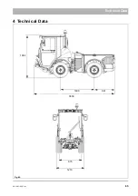
Page 85: ...04 1491 00 11 fm 85 Technical Data 4 Technical Data Fig 80 3830 1600 941 1210 975 1964...
Page 146: ...146 06 1491 00 12 fm Attachments and Options 6 1 5 Technical data Fig 144 2215 4510 1580 2250...
Page 220: ...220 06 1491 00 12 fm Attachments and Options...


