50
02-1491-00-11.fm
Operation
2.3.2
Left-hand control panel
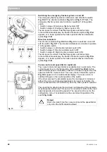
Switching on fresh water for the suction mouth
For binding dust the suction mouth is supplied with water from the circulat-
ing water system.
In addition, fresh water can be supplied to the suction mouth as required
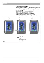
with the lever
Fig. 35-81
in the left-hand control panel.
Setting the fresh water volume for the sweeping unit
The volume of the fresh water at the spray nozzles is set with the lever
Fig. 35-82
in the left-hand control panel. Set the volume corresponding to
the requirements.
•
Light contamination: Reduce fresh water volume with the lever.
•
Heavy contamination: Increase fresh water volume with the lever.
2.3.3
Right-hand control panel
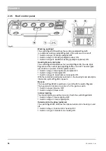
Raising and lowering the tipper body
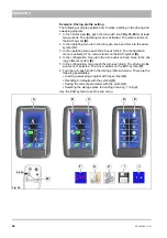
The following functions on the tipper body are switched on with the button
Fig. 36-75
:
•
Button in position
I
: Tipper body is raised until the button is released.
•
Button in position
II
: Tipper body is lowered until the button is released.
As long as the tipper body is not in its lower end position, the tipper body
raised warning symbol
appears.
Fig. 35:
81
82
Note
Switch the fresh water pump on in the configuration menu
before adjusting the fresh water volume, see page 41.
Note
Make sure that the ball cock for the circulating water is
opened, see page 62.
75
Fig. 36:
I
II
A
Danger
Danger to life in the danger area of the vehicle! Special cau-
tion is required in the area of the raised tipper body.
Note
For reasons of safety, the road speed is limited when the tip-
per body is raised (hopper or load platform)! With the tipper
body removed, the warning signal and the road speed limita-
tion must be deactivated for normal travel (configuration
menu, vehicle settings, see page 41). Each time the
button
Fig. 36-75
is pushed, the warning and safety function
is switched back on automatically.
Summary of Contents for Citymaster 1600
Page 22: ...22 01 1491 00 12 fm Safety Instructions G A B D E F Fig 3 C F C E C D G A B A...
Page 26: ...26 02 1491 00 11 fm Operation Fig 5 25 23 16 18 17 19 22 21 20 24 26 27...
Page 30: ...30 02 1491 00 11 fm Operation Fig 7 62 63 61 67 55 50 51 54 53 52 58 57 59 60 65 64 66 68 56...
Page 32: ...32 02 1491 00 11 fm Operation Fig 8 75 69 78 73 72 79 80 81 82 83 74 77 70 71 76 84...
Page 85: ...04 1491 00 11 fm 85 Technical Data 4 Technical Data Fig 80 3830 1600 941 1210 975 1964...
Page 146: ...146 06 1491 00 12 fm Attachments and Options 6 1 5 Technical data Fig 144 2215 4510 1580 2250...
Page 220: ...220 06 1491 00 12 fm Attachments and Options...


