06-1491-00-12.fm
191
Attachments and Options
6.5.1
Labels on the unit
Labels on the unit, see operating manual of the trailer.
6.5.2
Safety instructions
6.5.3
Assembly
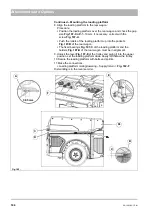
Mounting the trailer hitch plate (optional)
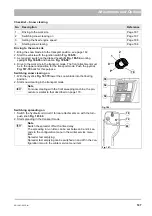
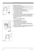
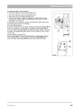
The trailer hitch plate
Fig. 191-101
is mounted without tools to the tail of
the vehicle.
1. Remove the locking pins
Fig. 191-B
of the four bolts
of the
trailer hitch plate and withdraw the bolts.
2. Position the trailer hitch plate on the vehicle.
3. Secure the trailer hitch plate with bolts and locking pins to the holding
of the vehicle tail.
4. If necessary, remove the footrest (optional) and collision protection
(optional).
5. Affix the Speed label at position
.
6. Close the valve
for the suction mouth lift system!
Danger
•
Danger to life in the danger area of the vehicle! Special caution is required in the area of the
articulated steering, under the raised tipper and in the area of the trailer.
•
Danger to life due to inadequately secured load! The load must be correctly distributed and
fastened on the loading surface.
•
Risk of injury! Modifying the safety equipment is not permitted.
•
Risk of accident! Adopt measures against erroneous starting and unwanted movement. Switch the
engine off and pull out the ignition key.
•
Risk of accident! You must consult Hako before attaching other attachments not approved by
Hako!
Warning
•
The transport system may be operated only in connection with the Citymaster 1600. The safety
regulations for the Citymaster 1600 must be complied with absolutely.
Caution
•
The labels attached to the vehicle provide important information for safe operation. Renew labels
that are no longer legible or present.
•
Spare parts must be original spare parts to guarantee safety.
Fig. 191:
B
C
D
X
E
101
Summary of Contents for Citymaster 1600
Page 22: ...22 01 1491 00 12 fm Safety Instructions G A B D E F Fig 3 C F C E C D G A B A...
Page 26: ...26 02 1491 00 11 fm Operation Fig 5 25 23 16 18 17 19 22 21 20 24 26 27...
Page 30: ...30 02 1491 00 11 fm Operation Fig 7 62 63 61 67 55 50 51 54 53 52 58 57 59 60 65 64 66 68 56...
Page 32: ...32 02 1491 00 11 fm Operation Fig 8 75 69 78 73 72 79 80 81 82 83 74 77 70 71 76 84...
Page 85: ...04 1491 00 11 fm 85 Technical Data 4 Technical Data Fig 80 3830 1600 941 1210 975 1964...
Page 146: ...146 06 1491 00 12 fm Attachments and Options 6 1 5 Technical data Fig 144 2215 4510 1580 2250...
Page 220: ...220 06 1491 00 12 fm Attachments and Options...

