


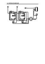
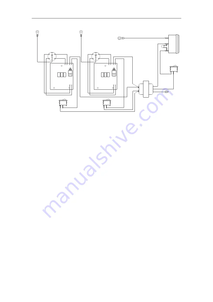
14. WIRING DIAGRAM
Black
Red
Black
White
Black
Varistor
Black
Red
Main power-supply
switch
Ground(Chassis)
Ground(Chassis)
Green/Yellow
Black
Black
Black
Black
White
White
White
White
Green/Yellow
Power receptacle
Green/Yellow
Red
Red
Switch
Black
Red
Switch
Ground(Chassis)
1
5
4
2
3
P.W.B.
Receptacle
H1
H2
26V 0V
SE1 SE2
Transformer
SE2
SE1
0V
26V
H2 H1
Receptacle
P.W.B.
3
2
4
5
1


