background image

6

17

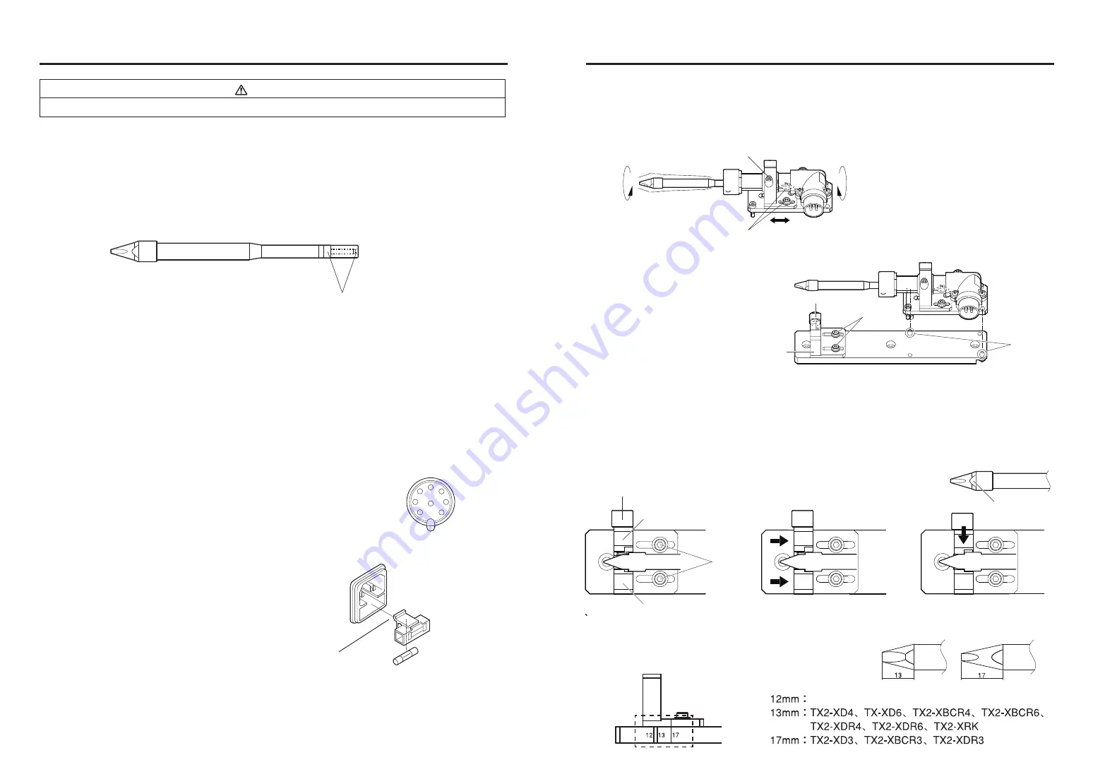
2. Loosen the following screws 

 and 

 and place the HAKKO FU-6002

    on the tip adjustment jig unit with the positioning pins aligned. 

3. Align the D-cut face of the tip with the pocket in the fixed side.

    Move the tip adjustment jig until the tip is fully inserted as shown in the following figure.

This position will be the reference point. Retighten the two screws 

①.

To prevent the upward movement and misalignment of the tip, tighten the screw 

 while pressing

    the tip from the top.

    Do not move the jig except for the one on the movable side and except for the time

    when the type of workpiece is changed. After the reference point has been set, 

    remove the HAKKO FU-6002 from the tip adjustment jig unit. 

● 

How to position the tip

1. To turn the shaft of the tip, loosen the positioning screw 

To move the soldering iron in the longitudinal direction, loosen the positioning screw 

Tighten the screws after determining the tip position balancing with your work object.

D-cut face

Movable side

Fixed side

Screw

Screw

9. CHECKING PROCEDURE

Check for a broken heater or sensor

Verify the electrical integrity of the heater and sensor.

Measure the resistance of the heater and sensor while at room temperature (15℃ to 25℃; 59℉ to 

77℉). It should be 3.

4Ω±10

. If the resistance exceeds these limits, replace it.

Check the grounding line

1. Unplug the iron cable from the station.

2. Measure the resistance between the pin 2 and tip with the iron cable connected to

the HAKKO FU-6002.

3. If the value exceeds 2Ω (at room temperature), perform the tip maintenance in page 15.

If the value still does not decrease, check the connection cord for breakage.

Check the iron cable for breakage

Measure the resistance of the pin.

Pin 1 to Pin 3

-

3.0 to 3.8Ω

If the resistance exceeds these limits, replace the iron cable.

Contact your HAKKO representative.

Replace the fuse

1. Unplug the power cord from the power receptacle.

2. Remove the fuse holder.

3. Replace the fuse.

4. Put the fuse holder back in place.

Measure the resistance across this position

1

4

7

2

8

5

6

3

Unless otherwise directed, carry out these procedures with power switch OFF and the power UNPLUGGED.

WARNING

 For shaft turning

 For longitudinal adjustment

positioning pin

Jig base

Tip adjustment jig

Screw

 Loosen

Screw

 Loosen

※ There are marking on the side of the tip adjustment jig unit.

The tip ends are classified into 12 mm, 13 mm and 17 mm. While referring to this marking,

adjust the position of the jig fixture.

Summary of Contents for FU-601

Page 1: ...HAKKO 4 2 5 5 6 http www hakkousa com HONG KONG HAKKO DEVELOPMENT CO LTD TEL 2811 5588 FAX 2590 0217 http www hakko com hk E mail info hakko com hk SINGAPORE HAKKO PRODUCTS PTE LTD TEL 6748 2277 FAX...

Page 2: ...ls 2 Be sure to ground the unit during use The temperature was measured using the FG 101 This product is protected against electrostatic discharge Specifications and design are subject to change witho...

Page 3: ...experience and knowledge unless they have been given supervision or instruction concerning use of the appliance by a person responsible for their safety Children should be supervised to ensure that th...

Page 4: ...all for the items to be soldered ACTION Use a tip with a larger thermal capacity CHECK Is the setting value for the low temperature alarm tolerance too low ACTION Increase the setting value Heater ter...

Page 5: ...ACTION See Checking the iron cable for breakage and Check for a broken heater or sensor in page 17 Replace any faulty part Solder does not wet the tip CHECK Is the tip temperature too high ACTION Set...

Page 6: ...is connected 10 ERROR MESSAGES Sensor error Low temperature alarm tolerance error Example 350 C 400 C 50 C Low temperature alarm tolerance Set temperature Soldering iron error When there is possibilit...

Page 7: ...ensor Measure the resistance of the heater and sensor while at room temperature 15 to 25 59 to 77 It should be 3 4 10 If the resistance exceeds these limits replace it Check the grounding line 1 Unplu...

Page 8: ...causing poor contact sensor error Regulary wipe off the flux using alcohol If wiping the flux protector did not remove the flux or dirt or the flux protector was deformed replace it Flux protector Par...

Page 9: ...ng depends upon the temperature the quality and quantity of the solder and flux Apply the following service procedure as dictated by the conditions of the usage Since the soldering iron can reach a ve...

Page 10: ...rom 0 to 5 can be selected when entering the hundreds digit In mode values from 1 to 9 can be selected Values from 0 to 9 can be selected when entering the tens or units digits The same values can be...

Page 11: ...ed Selects high output Selects normal output NOTE High power mode is mainly suited to applications that require large heat capacity such as quick soldering of ground patterns or cast metal products Se...

Page 12: ...units digit press the button to save the figure to the sytem memory and begin heater control with the new offset value Press and hold the button for at least one second Press the button once Prees the...

Page 13: ...units digit press the button to save the figure to the sytem memory and begin heater control with the new offset value Press and hold the button for at least one second Press the button once Prees the...

Page 14: ...ed Selects high output Selects normal output NOTE High power mode is mainly suited to applications that require large heat capacity such as quick soldering of ground patterns or cast metal products Se...

Page 15: ...rom 0 to 5 can be selected when entering the hundreds digit In mode values from 1 to 9 can be selected Values from 0 to 9 can be selected when entering the tens or units digits The same values can be...

Page 16: ...ng depends upon the temperature the quality and quantity of the solder and flux Apply the following service procedure as dictated by the conditions of the usage Since the soldering iron can reach a ve...

Page 17: ...causing poor contact sensor error Regulary wipe off the flux using alcohol If wiping the flux protector did not remove the flux or dirt or the flux protector was deformed replace it Flux protector Par...

Page 18: ...ensor Measure the resistance of the heater and sensor while at room temperature 15 to 25 59 to 77 It should be 3 4 10 If the resistance exceeds these limits replace it Check the grounding line 1 Unplu...

Page 19: ...is connected 10 ERROR MESSAGES Sensor error Low temperature alarm tolerance error Example 350 C 400 C 50 C Low temperature alarm tolerance Set temperature Soldering iron error When there is possibilit...

Page 20: ...ACTION See Checking the iron cable for breakage and Check for a broken heater or sensor in page 17 Replace any faulty part Solder does not wet the tip CHECK Is the tip temperature too high ACTION Set...

Page 21: ...e items to be soldered ACTION Use a tip with a larger thermal capacity CHECK Is the setting value for the low temperature alarm tolerance too low ACTION Increase the setting value Heater terminal shor...

Page 22: ...experience and knowledge unless they have been given supervision or instruction concerning use of the appliance by a person responsible for their safety Children should be supervised to ensure that th...

Page 23: ...sing the FG 101 This product is protected against electrostatic discharge Specifications and design are subject to change without notice 1 With 4XD tip 2 The dimension can be adjusted in range of 5mm...

Page 24: ...ENSIONAL OUTLINE DRAWING 13 EXPLODED VIEW 14 PARTS LIST 2017 2018 HAKKO Corporation All Rights Reserved 2018 2 MA02900XZ180202 17 1 0 8 5 3 1 2 8 5 13 4 1 5 8 5 13 6 65 15 120 8 5 17 3 13 4 120 8 5 13...

Reviews: