background image

7

6. OPERATION

A. Mode Selection

Insert the control card into the card slot and select 
your desired mode using the mode selection button. 
(Figure 10)
The HAKKO FR-803 provides the following two 
modes. The AUTO mode consists of the INSTALL 
and REMOVE modes.

  Manual Mode

In this mode, air and vacuum pump operation 
are controlled entirely by manual operation. 

NOTE:

The timer cannot be set when using MANUAL mode.

  AUTO mode

  Install Mode (AUTO) (See page 14.)

This mode is used when installing parts. 
The vacuum pump will be automatically 
turned OFF.

  Remove Mode (AUTO) (See page 13.)

This mode is used when removing parts.  
The vacuum pump will be automatically 
turned ON. 

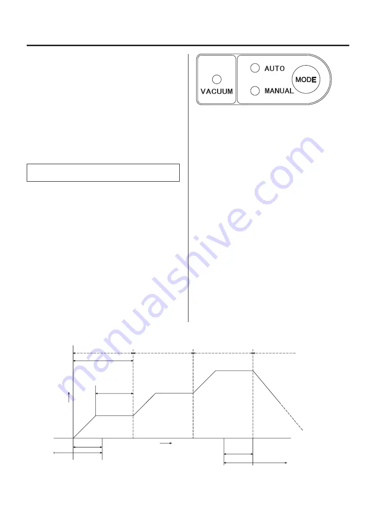
In INSTALL mode, turn ON the vacuum function 
manually and align the component on the PWB. 
Vacuum function automatically will turn OFF 5 
seconds after starting selected the profile.

In REMOVE mode, the vacuum function automati-
cally turns ON during the last 10 seconds of the 
selected profile.  
Set the temperature profile shown in the following 
figure in advance.

(Figure 10)

Step 1

Step 2

Step 3

Cool down

Air temperature

Timing when the vacuum pump is 

turned OFF in INSTALL mode

Start

Time

Temperatue 

is increasing.

Temperature 

is stable.

Temperature 

is stable.

Temperature

is decreasing.

When the tempera-

ture falls to 100°C 

(200°F), the air stops 

blowing automati-

cally.

Opend timer time

Closed timer time

Temperatue 

is increasing.

10 seconds

Timing when the vacuum pump is 

turned ON in REMOVE mode

5 seconds

*  In REMOVE mode, turn OFF the vacuum pump manually.

Temperatue 

is increasing.

Temperature 

is stable.

Summary of Contents for FR-803

Page 1: ...ead this manual before operating the HAKKO FR 803 Keep this manual readily accessible for reference TABLE OF CONTENTS 1 PACKING LIST 1 2 SPECIFICATIONS 1 3 WARNINGS CAUTIONS AND NOTES 2 4 PART NAMES 3...

Page 2: ...TIONS Name HAKKO FR 803 Power consumption 100V 310W 110V 370W 120V 440W 220V 590W 230V 650W 240V 700W Station Power consumption 100V 30 W 110 120V 40W 220 240V 50W Standby 100 120V 4W 220 240V 4W Capa...

Page 3: ...ng Do not direct the hot air toward personnel or touch the metal parts near the nozzle Do not use the product near combustible gases or flammable materials Advise those in the work area that the unit...

Page 4: ...mounting screw Airflow meter File number display Temperature Timer display Handpiece holder mounting screw Display steps Airflow control knob Mode selecting button Vacuum indicator Sensor internal Vac...

Page 5: ...The airflow can be set in the range of 5 to 20 l min This button displays and selects the MANUAL and AUTO modes This indicator lights the selected mode This indicator lights when the vacuum pump is in...

Page 6: ...en the nozzle mounting screw Pass the vacuum pipe through the nozzle hole and attach the nozzle Figure 5 d Tighten the nozzle mounting screw 2 Attach the pad a Attach the pad Figure 7 b Adjust the pad...

Page 7: ...5 c Tighten the nozzle mounting screw CAUTION The pad cannot be used with this type of nozzle C Electrical Connection and Power ON 1 Connect the power cord to the power receptacle on the back panel o...

Page 8: ...n the component on the PWB Vacuum function automatically will turn OFF 5 seconds after starting selected the profile In REMOVE mode the vacuum function automati cally turns ON during the last 10 secon...

Page 9: ...er is shut off and cooling begins When the temperature falls to 100 C 200 F the air stops blowing and the temperature display reads Vacuum Function This function is used to hold the component securely...

Page 10: ...value is displayed press the button The UNITS digit begins to ash 4 Enter the UNITS digit Select your desired value for the UNITS digit in the same manner as for the TENS digit When your desired value...

Page 11: ...eces sary to insert the control card 2 Pressing the HOT AIR button on the handpiece causes the unit to begin to blow and setting the temperature pro le causes it to start the le program 3 When all the...

Page 12: ...e Hot air blows from the nozzle to melt the solder The station operates based on the preprogrammed temperature pro le Figure 2 CAUTION To stop the program press the HOT AIR button Cooling begins Vacuu...

Page 13: ...le Figure 2 CAUTION To stop the program press the HOT AIR button Cooling begins Part suction When the timer runs down to 10 sec the vacuum automatically turns ON and the part is sucked Lift the handp...

Page 14: ...INSTALL or REMOVE selection mode 2 Use the or button to display Then press the button to select and shift to the step selection mode 3 Select your desired step using the or button Display your desire...

Page 15: ...igit begins to ash b Enter the HUNDREDS digit Use the or buttons to select your desired value for the TENS digit When your desired value is displayed press the button The UNITS digit begins to ash c E...

Page 16: ...digit on the temperature timer display section ashes Press the button to select The TENS digit begins to ash b Enter the TENS digit Use the or button to select your desired value for the TENS digit If...

Page 17: ...hen turning the airflow control knob G Set data checking method Setting in Auto mode Select your desired le No in advance Press the button Press and hold the button for more than 1 second Mode display...

Page 18: ...ted is not displayed the new setting value will not be stored in memory Parameter Parameter display Initial setting C F change C or F C C Power saving time 30 min 60 min 30 60 or 30 30 min Timer displ...

Page 19: ...gins to flash Enter the UNITS digit c Select your desired value for the UNITS digit in the same manner as for the TENS digit When your desired value is displayed press the button displays and indicate...

Page 20: ...uum pipe Measure the resistance value 1 Measure the resistance value a of the sensor The normal value is 0 2 Measure the resistance value b of the heater The normal values are approx imately 33 10 100...

Page 21: ...ON CHECK Is the power cord or connection plug discon nected ACTION Connect it CHECK Is the fuse blown ACTION Investigate why the fuse blew and then replace the fuse CHECK Is the sensor broken ACTION M...

Page 22: ...83 A1258B SOP 7 6 12 7 0 3 0 5 8 2 0 32 11 7 0 46 A1470 BGA 8 8 A1471 BGA 12 12 A1472 BGA 13 13 A1473 BGA 15 15 A1474 BGA 18 18 A1475 BGA 27 27 A1476 BGA 35 35 A1477 BGA 38 38 A1478 BGA 40 40 13 0 51...

Page 23: ...SOP 5 6 13 0 22 0 51 4 4 I D 0 17 4 8 0 19 10 0 39 5 7 0 22 15 0 59 7 2 0 28 16 0 63 A1134 SOP 7 5 18 0 3 0 7 7 2 0 28 19 0 75 A1142B Bent Single 1 5 3 0 06 0 12 45 1 5 0 0 6 I D 3 0 1 2 10 5 A1325 Du...

Page 24: ...India B2424 Power cord 3 wired cord European plug 220V KTL 230V CE B2425 Power cord 3 wired cord BS plug 230V CE U K B2426 Power cord 3 wired cord Australian plug B2436 Power cord 3 wired cord Chines...

Page 25: ...d assembly With silicone tube B1188 Silicone hose Tapping screw Nominal size 2 6 6 2 Item No Part No Part Name Specifications B3023 Vacuum pipe adjust ment knob L With screw B1354 Cord stopper for han...

Page 26: ...1 1 1 4 1 3 1 3 1 3 1 2 1 2 1 3 1 3 CN3 1 SW1 START SW2 VACUUM 1 2 1 3 14 WIRING DIAGRAM Transformer Pump Vacuum pump P W B Handpiece Power switch Power receptacle Pump Ground Heater Heating element...

Page 27: ...sa com HONG KONG HAKKO DEVELOPMENT CO LTD TEL 2811 5588 FAX 2590 0217 http www hakko com hk E mail info hakko com hk HEAD OFFICE TEL 81 6 6561 3225 FAX 81 6 6561 8466 http www hakko com E mail sales h...

Reviews: