First Edition: March 31, 2007
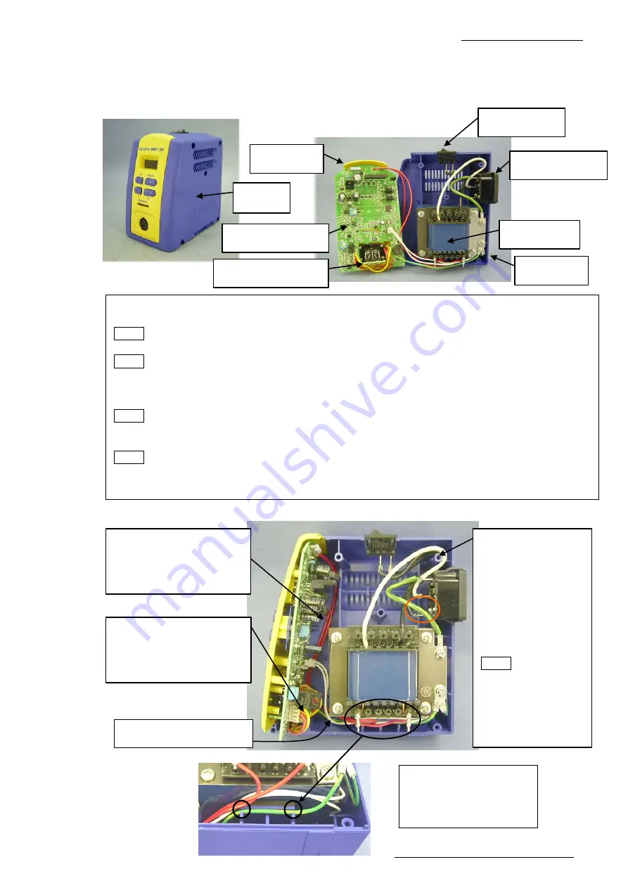
4-1 Opening the Cover (FX-951/FH-200)
Chapter 4
Disassembly Procedure
4-1
Opening the Cover
(1) Loosen 5 screws on the sides of the case R to remove the cover.
●
Assembly procedures (opening)
(1) Install the front panel in the case L. (Fig. 4-1-3)
NOTE Install the red lead wire and the lead wire for jack (white) carefully so that they do not
get caught.
NOTE Run the lead wire of P.W.B. (for control) outside the boss.
(2) Install the grounding wire for the P.W.B. in the designated place. (Figs. 4-1-3, 4-1-4)
(3) Install the lead wires for transformer, power switch and power receptacle outside the boss.
(Fig. 4-1-3)
NOTE Run the grounding wire not to let it come in contact with the power receptacle terminal.
(4) Cover the case L with the case R and secure them with 5 screws (P tight round head screw
M3 × 16) (Figs 4-1-3, 4-1-5 and 4-1-6)
NOTE Check that the cushion rubber B is installed in the case R and the cushion rubber A is
installed in the case L.
(5) Check that 2 rubber feet are installed in each of case R and L. (Fig. 4-1- 7)
Fig. 4-1-1
Case R
Fig. 4-1-2
P.W.B. (for control)
Power switch
Transformer
Front panel
Case L
P.W.B. (for connector)
Power receptacle
4-1-4
Fig. 4-1-3
Assembly procedure (2)
Install the lead wire of the
P.W.B. in the depressed
section in the case.
Assembly
procedure (3)
Run all the lead
wires for the
transformer, power
switch and power
receptacle outside
the boss.
NOTE Be careful
not to let the
grounding wire
come in contact
with the power
receptacle terminal.
Assembly procedure (1)
Install the lead wire of the
P.W.B. (for connector)
outside the boss.
Assembly procedure (1)
Be careful not to let the red
lead wire of the P.W.B. get
caught on the front panel.
Lead wire for jack (white)


