background image

Service manual

T13

2


INDEX                                                                                  PAGE 


COMPONENTS                                                                       3    


                                                 9                                                                                                                 


DISASSEMBLY 

                                                                     52 


REPAIR TECH 

                                                        71                                                                                                                           


MEASURING VALUES FROM THE COMPONENTS 


SERVICE FAILURE CODES  


/60 HZ

Summary of Contents for T13

Page 1: ...Dishwasher T13 Service Manual EN ...

Page 2: ...Service manual T13 2 INDEX PAGE COMPONENTS 3 9 DISASSEMBLY 52 REPAIR TECHNIQUES 71 MEASURING VALUES FROM THE COMPONENTS SERVICE FAILURE CODES ...

Page 3: ...Service manual T13 3 60 HZ ...

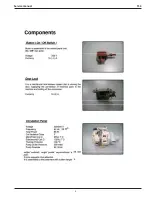
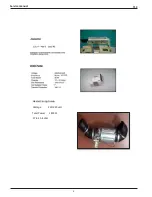
Page 4: ...Service manual T13 4 Heater Casing Group Voltage 220 240 volt Total Power 1800W 27 6 30 6 ohm ...

Page 5: ...Service manual T13 5 NTC with Thermal Protector Pressure Switch Voltage 220 240 v Frequency 50 60 Hz 16 A 3 Pins ...

Page 6: ...Service manual T13 6 ...

Page 7: ...Service manual T13 7 60HZ ...

Page 8: ...Service manual T13 8 ...

Page 9: ...Service manual T13 9 ...

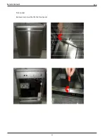
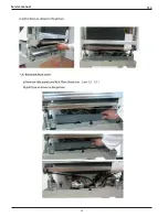
Page 10: ...Service manual T13 10 Front panel Remove six screws that fix the front panel ...

Page 11: ...Service manual T13 11 ...

Page 12: ...Service manual T13 12 ...

Page 13: ...Service manual T13 13 ...

Page 14: ...Service manual T13 14 ...

Page 15: ...Service manual T13 15 ...

Page 16: ...Service manual T13 16 ...

Page 17: ...Service manual T13 17 ...

Page 18: ...Service manual T13 18 ...

Page 19: ...Service manual T13 19 ...

Page 20: ...Service manual T13 20 ...

Page 21: ...Service manual T13 21 ...

Page 22: ...Service manual T13 22 ...

Page 23: ...Service manual T13 23 ...

Page 24: ...Service manual T13 24 ...

Page 25: ...Service manual T13 25 ...

Page 26: ...Service manual T13 26 ...

Page 27: ...Service manual T13 27 ...

Page 28: ...Service manual T13 28 ...

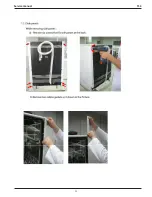
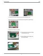
Page 29: ...ice manual T13 29 2 6 LED MODUL Opsionel a Remove the right side panel b Remove the electrical connections as in the picture c LED modules behind the nut by turning it counter clockwise direction to remove ...

Page 30: ...Service manual T13 30 ...

Page 31: ...Service manual T13 31 ...

Page 32: ...Service manual T13 32 ...

Page 33: ...Service manual T13 33 ...

Page 34: ...Service manual T13 34 ...

Page 35: ...Service manual T13 35 ...

Page 36: ...Service manual T13 36 ...

Page 37: ...Service manual T13 37 ...

Page 38: ...Service manual T13 38 ...

Page 39: ...Service manual T13 39 ...

Page 40: ...Service manual T13 40 ...

Page 41: ...Service manual T13 41 ...

Page 42: ...Service manual T13 42 ...

Page 43: ...Service manual T13 43 ...

Page 44: ...Service manual T13 44 ...

Page 45: ...Service manual T13 45 ...

Page 46: ...Service manual T13 46 ...

Page 47: ...Service manual T13 47 ...

Page 48: ...Service manual T13 48 ...

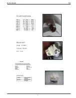
Page 49: ...Service manual T13 49 VALUES OF PUMP COILS ACC WASHING POMP WELLİNG WASHING POMP MAİN COİL 95 Ω 7 MAİN COİL 120 Ω 7 SUB COİL 125 Ω 7 SUB COİL 116 Ω 7 ...

Page 50: ...Service manual T13 50 ...

Page 51: ...Service manual T13 51 VALUES OF PUMP COILS PLASET DRAİN PUMP HANYU DARİN PUMP 143 Ω 7 210 Ω 6 ...

Page 52: ...Service manual T13 52 ...

Page 53: ...Service manual T13 53 WATER INLET VALVES OPTIONAL 3750 Ω 10 20 ...

Page 54: ...Service manual T13 54 ...

Page 55: ...Service manual T13 55 ...

Page 56: ...Service manual T13 56 ...

Page 57: ...Service manual T13 57 ...

Page 58: ...Service manual T13 58 ...

Page 59: ...Service manual T13 59 ...

Page 60: ...Service manual T13 60 ...

Page 61: ...Service manual T13 61 ...

Page 62: ...Service manual T13 62 ...

Page 63: ...Service manual T13 63 ...

Page 64: ...in hose maximum height 110 cm Drain hose minimum height 50 cm Drain hose maximum length 400 cm 2 2 Water Inlet Hose Hose that is flat edge is assemblied to plug Another edge that is turned edge is assemblied to water inlet valve It must be adjusted for assembly direction ...

Page 65: ...ervice if the error resumes Error of continuous water input Close the tap Contact the service The waste water in the machine cannot be discharged Water discharge hose is clogged The filters of your machine might be clogged Power off on your machine and activate the program cancellation command If the error continues contact the service Intended water temperature could not be reached faulty heater ...

Page 66: ...lose the tap Contact the service F2 The waste water in the machine cannot be discharged Water discharge hose is clogged The filters of your machine might be clogged Power off on your machine and activate the program cancellation command If the error continues contact the service F8 Heater error Contact the service F1 Alarm is active against water overflow Power off your machine and close the tap C...

Page 67: ...t 4 20 If during the service test the door is opened start pause led blinks in T12 T13 T21 also SP is shown If during the service test the start pause button is pressed the program corresponding at the knob position starts Service Failure Codes Coding service failure for T11 Note T11 will also include the coding service failure for T12 T13 T21 Step Time Tested Load 0 SP Show code 6 Before start th...

Page 68: ...nce of Flow meter F4 In the normal work this failure is not visualized Empty Level F5 Re Fill time out F5 NTC ca cc F6 Overheating F7 Unsuccessful heating F8 Diverter opened F9 Turbidity Sensor FA In the normal work this failure is not visualized Parameter set salt incorrect SE In the normal work this failure is not visualized CK Parameter FE Note T12 T13 T21 will also include the coding service f...

Page 69: ...Service manual T13 69 ...

Page 70: ...Service manual DW T13 ...

Reviews: