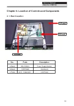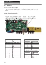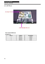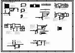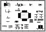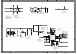
CON3 CON4
LED driver
connector
Pin number
Signal name
1
+
2
-
3
NC
+
Backlight adjust connector
1
BL_ON
2
ADJ
3
GND
AMP power connector
1
GND
2
GND
3
VCC
4
VCC
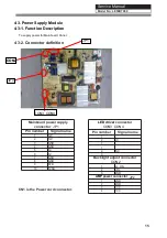
Mainboard power supply
connector
Pin number
Signal name
1
12V
2
12V
3
GND
4
GND
5
5V
6
5V
7
GND
8
GND
9
STB
10
5VSB
Service Manual
Model No.:
4-3. Power Supply Module
4-3-1. Function Description
To supply power for Mainboard, Panel.
4-3-2. Connector denition
CN1 is the Power cord connector.
15
LE50B7000
CON3 CON4
CON2
JP2
JP1
CON3 CON4
JP2
CON2
JP1
-
1
2
NC
3
-
CON2
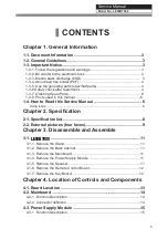
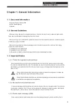
Summary of Contents for LE50B7000
Page 10: ...Service Manual Model No 2 2 External pictures four faces Front Side Up Side 9 LE50B7000 ...
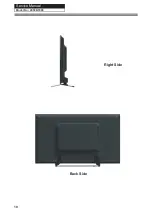
Page 11: ...Service Manual Model No Right Side Back Side 10 LE50B7000 ...
Page 18: ...Service Manual Model No 17 LE50B7000 ...
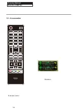
Page 19: ...P SIZE Batteries RemoteControl 5 1 Accessories Service Manual 18 Model No LE50B7000 ...
Page 30: ...Service Manual Model No 7 2 Wiring Connection Diagram 30 LE50B7000 ...
Page 36: ...Service Manual Model No 9 2 Mainboard IC Introduction Top view 36 1 2 3 4 5 6 7 8 LE50B7000 ...
Page 37: ...Service Manual Model No Bottom view 37 LE50B7000 ...

