


32
″
LCD TV Haier L32C1120
1
Service
Service
Service
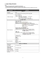
Horizontal Frequency
31~75 KHz
TABLE OF CONTENTS
Description
Page Description Page
SAFETY NOTICE
ANY PERSON ATTEMPTING TO SERVICE THIS CHASSIS MUST FAMILIARIZE HIMSELF WITH THE CHASSIS
AND BE AWARE OF THE NECESSARY SAFETY PRECAUTIONS TO BE USED WHEN SERVICING
ELECTRONIC EQUIPMENT CONTAINING HIGH VOLTAGES.
CAUTION: USE A SEPARATE ISOLATION TRANSFOMER FOR THIS UNIT WHEN SERVICING
6.3 Led Board………………………..……..……….......34
6.4 Key Board………………………..……..……….......34
6.5 IR Board…………………………..……….…….......35
7. Adjustment……………….……….…………...………36
7.1 ADC Adjustment……………………..……...………36
7.2 FW Upgrade.………………………………...………37
7.3 The Writing VGA & HDMI EDID….………...………41
8. Block Diagram.…….................................................46
9. Wiring Diagram.……...............................................47
10. Schematic Diagram………..……..………………...48
10.1 Main Board…………….…………………...….......48
10.2 Power Board………..…....…………...……….......60
10.3 Led Board……………………..……..……….......62
10.4 Key Board……………….………….………….......63
10.5 IR Board……………………………….……….......64
Table of Contents.......……....................................…........1
Important Safety Notice.......................................……......2
Revision List…………………………………………………3
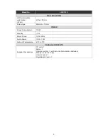
1. General Specification.................................………........4
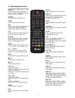
2. Operating Instructions…………………….……...….......6
2.1 The Use of Remote Control…….…………...…….......6
2.2 To Use the Menus…...………………….….………......7
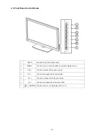
2.3 Front Panel Control Knobs……………….………......15
2.4 How to Connect…….…………………….…..…….....16
3. Input/Output Specification…………....................…....17
4. Mechanical Instructions…………………….................19
5. Repair Flow Chart ………………………………………22
6. PCB Layout …………...………………………………...29
6.1 Main Board………..…………………...……….….......29
6.2 Power Board……..…………..………….…..…….......31
Summary of Contents for L32C1120
Page 7: ...7 2 2 To Use the Menus ...
Page 8: ...8 ...
Page 9: ...9 ...
Page 10: ...10 ...
Page 11: ...11 ...
Page 12: ...12 ...
Page 13: ...13 ...
Page 14: ...14 ...
Page 20: ...20 Step3 Remove the POWER CORD Step4 Remove the MAIN BOARD POWER BOARD and SPEAKERS ...
Page 29: ...29 6 PCB Layout 6 1 Main Board 715G3269M01001005K ...
Page 30: ...30 ...
Page 31: ...31 6 2 Power Board 715G3770P02W20003S ...
Page 32: ...32 ...
Page 33: ...33 ...
Page 34: ...34 6 3 LED Board 715G4252T02000004S 6 4 Key Board 715G4234K02000004S ...


