Choose Your Connection
There are several ways to connect your television,
depending on the components you want to connect and
the quality of the signal you want to achieve.
The following are examples of someways to connect
your TV. Choose the connection which is best for you.
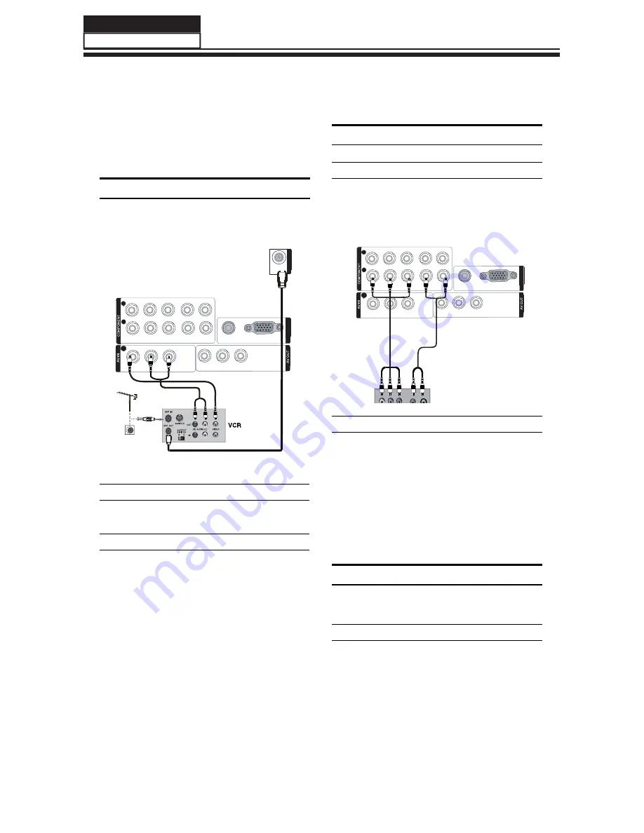
VCR Connection
To avoid picture noise (interference), leave an adequate
distance between the VCR and TV.
select the source, press the
button to confirm.
DVD Setup
How to connect
Connect the DVD video outputs (Y, P
A
b
/C
b
, P
r
/C
r
)
to the COMPONENT (Y, P
b
/C
b
, P
r
/C
r
) input jacks on
the TV and connect the DVD audio outputs to the
AUDIO jacks on the TV as shown in the figure.
Y Pb/Cb Pr/Cr L-AUDIO-R
IN
1
2
VIDEO
L-AUDIO-R
VIDEO
L-AUDIO-R
VGA/DVI AUDIO
VGA
VGA
IN
2
How to use
Turn on the DVD player, insert a DVD .
A
Use the
B
INPUT
button on the remote control,and
then press
button to to select COMPONENT
mode, press the
button to confirm.
Press
C
Play
button on external equipment for
program play.
Refer to the DVD player’s manual for operating
D
instructions.
HDMI or DVI Setup
To watch digitally broadcast programs, purchase and
connect a digital set-top box.
How to connect
Use the TV’s COMPONENT (Y, P
•
b
/C
b
, P
r
/C
r
) INPUT
jacks, VGA or HDMI port for video connections,
depending on your set-top box connections
ANT IN
VIDEO
L-AUDIO-R
VIDEO
L-AUDIO-R
VGA/DVI AUDIO
VGA
VGA
IN
2
Y Pb/Cb Pr/Cr L-AUDIO-R
IN
1
2
Connection Option 1
Set VCR output switch to channel 3 or 4 and then tune
the TV to the same channel number.
Connection Option 2
Connect the audio and video cables from the VCR’s
A
output jacks to the TV input jacks, as shown in the
figure. When connecting the TV to VCR, match the
jack colors (Video = yellow, Audio Left = white, and
Audio Right = red).
Insert a video tape into the VCR and press
B
PLAY
on
the VCR. (Refer to the VCR owner’s manual.)
Select the input source using the
C
INPUT
button
on the remote control, and then press
/
to
&+ &+
button
2.
GLVF
/
&+ &+
2.
S
ervice M
a
nu
a
l
Model No.:
/)
3
6
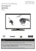
Summary of Contents for L26F6
Page 10: ...2 2 External pictures four faces Front Side Left Side 2 2 1 9 L26F6 Service Manual Model No ...
Page 11: ...10 Right Side Back Side Service Manual Model No ...
Page 12: ...Front Side Left Side 2 2 2 11 L32F6 Service Manual Model No ...
Page 13: ...12 Right Side Back Side Service Manual Model No ...
Page 14: ...Front Side Left Side 2 2 3 L42F6 Service Manual Model No 13 ...
Page 15: ...Right Side Back Side Service Manual Model No 14 ...
Page 58: ...8 2 3 Audio This page is control the sound effect QRQOLQHDU YROXPH Service Manual Model No 57 ...


