2
2
1
1
1
1
Y
Y
Pb
Pb
Pr
Pr
L
L
R
R
L
L
L
L
R
R
R
R
VIDEO
VIDEO
VIDEO
VIDEO
S-VIDEO
S-VIDEO
VGA
VGA
VGA AUDIO
VGA AUDIO
AUDIO
AUDIO
AUDIO
AUDIO
L
L
R
R
DVI AUDIO
DVI AUDIO
AUDIO
AUDIO
2
2
L
L
R
R
AUDIO
AUDIO
C
O
M
P
O
N
E
N
T
I
N
C
O
M
P
O
N
E
N
T
I
N
V
ID
E
O
I
N
V
ID
E
O
I
N
1
1
A
V
O
U
T
A
V
O
U
T
V
G
A
I
N
V
G
A
I
N
H
D
M
I
IN
H
D
M
I
IN
A
N
T
I
N
A
N
T
I
N
O
P
T
IC
A
L
O
U
T
O
P
T
IC
A
L
O
U
T
2
2
1
1
1
1
Y
Y
Pb
Pb
Pr
Pr
L
L
R
R
L
L
L
L
R
R
R
R
VIDEO
VIDEO
VIDEO
VIDEO
S-VIDEO
S-VIDEO
VGA
VGA
VGA AUDIO
VGA AUDIO
AUDIO
AUDIO
AUDIO
AUDIO
L
L
R
R
DVI AUDIO
DVI AUDIO
AUDIO
AUDIO
2
2
L
L
R
R
AUDIO
AUDIO
C
O
M
P
O
N
E
N
T
I
N
C
O
M
P
O
N
E
N
T
I
N
V
ID
E
O
I
N
V
ID
E
O
I
N
1
1
A
V
O
U
T
A
V
O
U
T
V
G
A
I
N
V
G
A
I
N
H
D
M
I
IN
H
D
M
I
IN
A
N
T
I
N
A
N
T
I
N
O
P
T
IC
A
L
O
U
T
O
P
T
IC
A
L
O
U
T
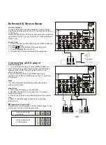
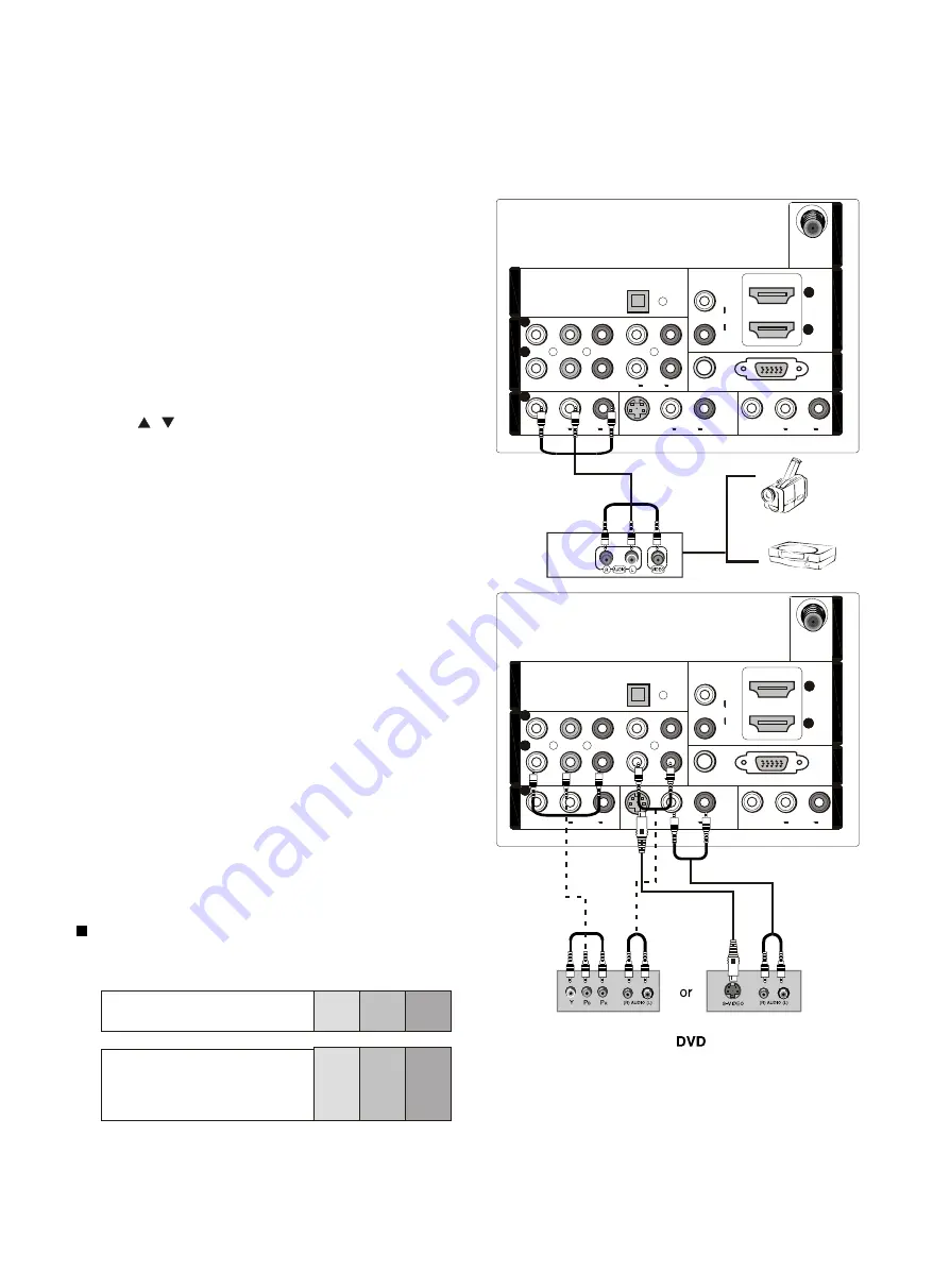
How to connect
1. Connect the DVD video outputs (COMPONENT) to
the Y Pb Pr jacks on the TV and connect the DVD audio
outputs to the YPbPr Audio IN jacks on the TV, as
shown in the figure.
2. If your DVD only has an S-VIDEO output jack,
connect this to the S-VIDEO input on the TV. as shown
in the figure.
Note
If your DVD player does not have component video
output, use S-Video.
How to use
1. Turn on the DVD player, insert a DVD.
2. Use INPUT button on the remote control to select
component mode.
3. Press Play button on external equipment for program
play.
4. Refer to the DVD player's manual for operating
instructions.
How to connect
Connect the audio and video cables from the external
equipment's output jacks to the TV input jacks, as shown
in the figure.
When connecting the TV to external equipment, match the
jack colors (Video = yellow, Audio Left = white, and Audio
Right = red).
How to use
1. Select the input source with using the INPUT button on
the remote control.
2. Press / button to select the desired source.
3. Press
button to confirm.
4. Operate the corresponding external equipment.
ENTER
Video Game Set
Camcorder
Component Input ports
To get better picture quality, connect a DVD player to the
component input ports as shown below.
Component ports
on the TV
Video output ports
on DVD player
Y Pb Pr
Y Pb Pr
Y B-Y R-Y
Y Cb Cr
Y P P
B
R
External A/V Source Setup
Connecting a DVD player
Summary of Contents for HLC32R1 - 32" LCD TV
Page 10: ...CON3 CON4 CON5 ...
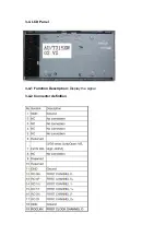
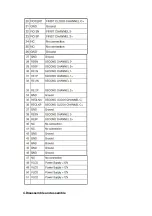
Page 11: ...3 4 LCD Panel 3 4 1 Function Description Display the signal 3 4 2 Connector definition ...
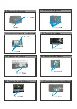
Page 12: ...4 Disassemble and assemble ...
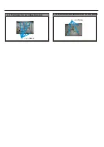
Page 14: ...4 9 Remove the terminal bracket Screw Screw 4 10 Remove the connection to the panel ...
Page 26: ...7 Electrical parts 7 1 Block diagram 7 2 Circuit Diagram MTK5380L MT8292 TPA3101 ...
Page 42: ......
Page 48: ...42 Clean Storage The function could make the model turn back to the factory default setting ...

