background image

12

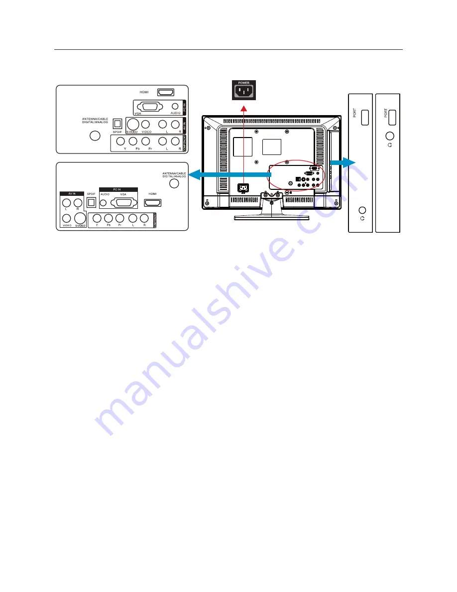
PERIPHERAL CONNECTION GUIDE

For HL19D2 / HL24XD2

USB

USB

AC POWER

HL19D2

HL19D2

HL24XD2

HL24XD2

HDMI

1. 

 – Connect the primary source for digital video such as a DVD multimedia player or 

set top box through this all digital connector.

PC IN

2. 

 – Connect the video and audio cables from a computer here.

AV IN (AV/S-VIDEO)

3. 

 – Connect the input source for composite video devices, such as a 

VCR or video game. Use the white and red connectors to connect the external audio from 
the same source. The signal being carried by the S-Video cable and connector, if connected, 
will take priority over the Video RCA connector (yellow connector).

COMPONENT (Y/Pb/Pr with Audio L/R)

4. 

 – Connect the primary source for component 

video devices such as a DVD Player or set top box here. Use red for Pr, blue for Pb, green for Y, 
red for right audio (R) and white for left audio (L) inputs.

ANTENNA/CABLE DIGITAL/ANALOG

5. 

 – Connect to an antenna or digital cable (out-

of-the-wall, not from Cable Box) for Digital TV.

SPDIF (Optical Digital Audio Out)

6. 

 – When a digital audio signal is associated with the 

input  selected for viewing, the digital audio will be available on this SPDIF connection to 
your home theater system.

USB PORT

7. 

 – Insert USB storage device to the USB port to view photos or listen to music.

Earphone Output

8. 

 – Connect to the headphones. When the headphone is inserted to the 

plug, all the speakers will be muted.

Once your equipment is connected, use the following procedure to view the input signal:
Press the Source button on the remote control to select the relevant source to view. (ex: Press Comp 
button to select “Component” if you have connected a video recorder to Component socket.)

Summary of Contents for HL32D2

Page 1: ...R TFT LCD TV OWNER S MANUAL Please READ this manual carefully before operating your TV and retain it for future reference MODELS HL19D2 HL24XD2 HL32D2 HL42XD2...

Page 2: ...onando como antes para otros usos por ejemplo para ver emisoras de TV de baja potencia que todav a transmiten en anal gico para ver pel culas pregrabadas o para utilizar sus videojuegos Para obtener m...

Page 3: ...rticular installation If this equipment does cause harmful interference to radio or television reception which can be determined by turning the equipment off and on the user is encouraged to try to co...

Page 4: ...ore cleaning Do not use liquid cleaners or aerosol cleaners to clean the display Make sure to unplug the unit when not in use for a long period of time days Do not cover or block any vents and opening...

Page 5: ...from tip over The TV should be operated only from the type of power source indicated on the label If you are not 13 sure of the type of power supplied to your home consult your dealer or local power...

Page 6: ...nger yourself or children by placing electronic equipment toys on the top of the cabinet Such items could unsuspectingly fall from the top of the set and cause product damage and or personal injury Wa...

Page 7: ...to use manual will guide you in getting the best use of your product Remember to record the model and serial number They are on label in back of the unit Model number Serial number Date of purchase S...

Page 8: ...HING THE BASE 9 PREPARINGYOUR LCD HDTV FOR WALL MOUNTING 9 PERIPHERAL CONNECTION GUIDE 12 OPERATING INSTRUCTIONS 14 TO USE THE FRONT PANEL CONTROL 14 TO USE THE REMOTE CONTROL 15 TO USE THE MENUS 16 C...

Page 9: ...rt the screws to the bottom of the 3 base and tighten the base to the stand PREPARINGYOUR LCD HDTV FOR WALL MOUNTING We suggest that you keep your TV at least 2 36 inches 60 mm from the wall to preven...

Page 10: ...cover of the stand Remove the screw that secure the stand to 2 your TV and remove the stand Secure the wall mount bracket to the 3 back of your TV using four M6 screws as indicated in the illustratio...

Page 11: ...uipment shall not be exposed to dripping or splashing Connect the antenna cable or CATV cable 2 to the aerial socket ANT IN 75 at the back of the TV set Remote control 3 Remove the cover of the batter...

Page 12: ...D Player or set top box here Use red for Pr blue for Pb green forY red for right audio R and white for left audio L inputs ANTENNA CABLE DIGITAL ANALOG 5 Connect to an antenna or digital cable out of...

Page 13: ...inputs ANTENNA CABLE DIGITAL ANALOG 5 Connect to an antenna or digital cable out of the wall not from Cable Box for Digital TV SPDIF Optical Digital Audio Out 6 When a digital audio signal is associa...

Page 14: ...ume level 3 CH Press to select the next higher program number 4 CH Press to select the next lower program number 5 MENU Press to open or exit the OSD on screen display menu 6 INPUT Press to select the...

Page 15: ...CH Comp PC HDMI TV Sleep Fav Source Mute Menu Exit ENTER V Chip Video Adj Audio Adj C C Info VOL CH EPG Freeze MTS SAP TO USETHE REMOTE CONTROL Power Press to power ON OFF standby TV Note 1 TV is neve...

Page 16: ...ly FAV Channel Setting 7 Show the Favorite Channel List User can edit add delete the favorite channels VIDEO MENU TheVideo menu in most source modes shows as below It provides several video adjustment...

Page 17: ...dify the audio setting Audio language setting is only available with ATSC TV source the option is disable under other source modes ENTER Exit Menu AUDIO Sound Mode Bass Treble Audio Language Balance 3...

Page 18: ...n Parental Locks Off Off Button Lock Select On or Off to lock or unlock the control buttons on the side panel of the TV When this function enables the control buttons on your TV will be locked and TV...

Page 19: ...Music On Slide Show Enable background Music during slide show It will play with the MP3 file sequence in current folder repeatedly Music On Slide Show item will be grayed out if there is no MP3 file i...

Page 20: ...lid in MP3 media player interface only After setting to On state backlight will be turned off automatically after 10 seconds no any key pressed Press any key to turn on the TV immediately but if there...

Page 21: ...designed to provide reasonable protection against harmful interference in a residential installation This equipment generates uses and can radiate radio frequency energy and if not installed and used...

Page 22: ...AV S Video and L R audio input PC IN D SUB and PC Audio Headphone mini jack Supported scan rate 640x480 60 72 75Hz 720x400 70Hz 800x600 56 60 72 75Hz 1024x768 60 70 75Hz 1280x720 60Hz 1280x768 60Hz 16...

Page 23: ...2 5 Kg 20 5 Kg Weight without Stand and Base 3 85 Kg 5 4 Kg 10 6 Kg 17 6 Kg WALL MOUNTING VESA compatible wall bracket W x H 100 x 100 mm 100 x 100 mm 200 x 200 mm 400 x 200 mm Screw type Metric 4 x 1...

Page 24: ...her channel Adjust the contrast and brightness settings Check the Closed Captions control Some TEXT modes could block the screen Good picture but no sound Increase theVOLUME Check if the TV is muted p...

Page 25: ...ultichannelTelevision Sound MTS The broadcasting standard which allows stereo sounds to be transmitted with theTV picture RF Radio Frequency or modulated signal design used as the carrier for televisi...

Page 26: ...any warranties beyond the time period described herein on behalf of Haier WARRANTY The warranties described herein shall be the sole and exclusive warranties granted by Haier and shall be the sole an...

Page 27: ......

Page 28: ...R 01 0090506421A...

Reviews: