


508145-01G / 31-5000660
Page 30 of 38
Issue 2220
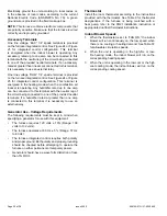
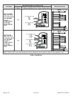
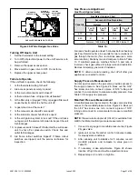
On-Board Link W951 Heat Pump (R to O)
On-board link W951 is a clippable connection between
terminals R and O on the integrated control. W951 must
be cut when the furnace is installed in applications which
include a heat pump unit and a thermostat which features
dual fuel use. If the link is left intact, terminal “O” will remain
energized eliminating the HEAT MODE in the heat pump.
On-Board Link W915 2 Stage Compr (Y1 to Y2)
On-board link W915 is a clippable connection between
terminals Y1 and Y2 on the integrated control. W915 must
be cut if two-stage cooling will be used. If the Y1 to Y2
link is not cut the outdoor unit will operate in second-stage
cooling only.
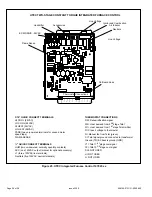
Diagnostic Push Button
The diagnostic push button is located adjacent to the seven-
segment diagnostic LED. This button is used to enable
the Error Code Recall “E” mode and the Flame Signal “F”
mode. Press the button and hold it to cycle through a menu
of options. Every five seconds a new menu item will be
displayed. When the button is released, the displayed item
will be selected. Once all items in the menu have been
displayed, the menu resumes from the beginning until the
button is released.
Unit Start-Up
FOR YOUR SAFETY, READ BEFORE LIGHTING UNIT
Do not use this furnace if any part has been underwater.
A flood-damaged furnace is extremely dangerous.
Attempts to use the furnace can result in fire or explosion.
Immediately call a qualified service technician to inspect
the furnace and to replace all gas controls, control
system parts, and electrical parts that have been wet or
to replace the furnace, if deemed necessary.
WARNING
If overheating occurs or if gas supply fails to shut off,
shut off the manual gas valve to the appliance before
shutting off electrical supply.
WARNING
Before attempting to perform any service or
maintenance, turn the electrical power to unit OFF at
disconnect switch.
CAUTION
BEFORE LIGHTING
smell all around the appliance area
for gas. Be sure to smell next to the floor because some
gas is heavier than air and will settle on the floor.
The gas valve on this unit will be equipped with a gas
control switch. Use only your hand to move the switch.
Never use tools. If the switch will not turn or if the control
switch will not move by hand, do not try to repair it.
Placing the Furnace into Operation
These units are equipped with an automatic ignition
system. Do not attempt to manually light burners on these
furnaces. Each time the thermostat calls for heat, the
burners will automatically light. The ignitor does not get hot
when there is no call for heat on units with an automatic
ignition system.
If you do not follow these instructions exactly, a fire
or explosion may result causing property damage,
personal injury or death.
WARNING
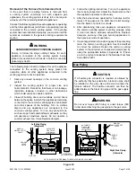
Gas Valve Operation
1.
STOP!
Read the safety information at the beginning
of this section.
2. Set the thermostat to the lowest setting.
3.
Turn off all electrical power to the unit.
4. This furnace is equipped with an ignition device which
automatically lights the burners. Do not try to light the
burners by hand.
5. Remove the upper access panel.
6. Move switch on gas valve to OFF. Do not force. See
7.
Wait five minutes to clear out any gas. If you then
smell gas,
STOP!
Immediately call your gas supplier
from a neighbor’s phone. Follow the gas supplier’s
instructions.
8. Move switch on gas valve to ON. Do not force. See
9. Replace the upper access panel.
10. Turn on all electrical power to to the unit.
11. Set the thermostat to desired setting.
NOTE:
When unit is initially started, steps 1 through
11 may need to be repeated to purge air from gas line.
12. If the appliance will not operate, follow the instructions
“Turning Off Gas to Unit” and call your service
technician or gas supplier.


