


HAIER CHILLER
10. Wiring diagram
t and slave control diagram, each diagram included
diagram are used for any combination, because the quantity of fan motor and address of input/output are
defferent, wiring diagram of the six basic modules is not completely same, but the basic control is similar.
Take CI0386AANB as example:
1. Combination type: CI0386AANB=CI0CI0193AANC
one is used
2. Control 4 condensing fan motor, which is divided to 2 groups and controlled by contactor and relay, the wiring
digram is as following:
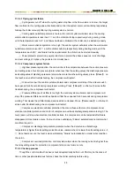
10.1 Main control circuit
1) 386 main control return circuit: it is the sketch map for compressor, fan motor and PCB power supply mostly.
Touch screen 24V DC power
Control part of strong power
Main control 193
have
have
Slave control 193
none
none
same
R2 S2 T2
V1
M1-2
COM
14
1
NO
12
11
NC
100
Y
X
Z
KM3
U1
S11
ABJ1-14
R
R11
6
T
4
S
5
T11
FU6
FU5
FU7
R
T
S
PA
95
A
PE
FR1
U V W
M
KM1
KM2
FR2
KM4
S1
QF1
R1
T1
QF2
M3-4
W1
V2
U2
W2
DR
GP
+
205
60
102
V+
V-
N
L
-
0
R5 T5
R3 S3 T3
FR3
KM5
66
KM7
65
QF3
QF5
H1
FU4
FU3
DF0
R1
KM2
R30
SEM
Q1
67
KM1
R10
KM1 200
201
fan
FJ
FU2
R21
FU1
BT
T21
T31
power indicator
electric heater
liquid supply
solenoid valve
emergency button
heater
No.2 fan
motor
No.1 fan
motor
compressor
power
supply
3
R31
The wiring diagram can be devided as main control circui
three parts: main control return circuit, PCB circuit and terminal connection diagram. The two type wiring
, one is used as main control, the other
as slave control, the main configuration differenceis as following:
6


