18
Installation procedure
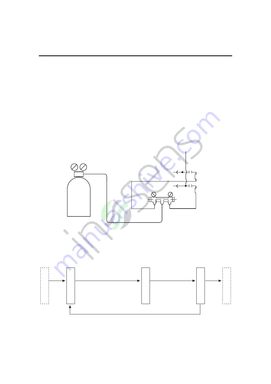
B. Leakage test
C. Evacuation
1. The outdoor unit has been executed the leakage test in the factory. The pipe should be
executed leakage test individually and forbidden to test after connecting with stop valve.
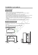
2. Refer to the below
fi
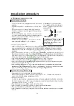
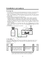
gure to charge the nitrogen into the unit to take a test. Never use the
chlorin, oxygen,
fl
ammable gas in the leakage test. Apply pressure both on the gas pipe and
the liquid pipe.
3. Apply the pressure step by step to the target pressure.
a. Apply the pressure to 0.5MPa for more than 5 minutes, con
fi
rm if pressure goes down.
b. Apply the pressure to 1.5MPa for more than 5 minutes, con
fi
rm if pressure goes down.
c. Apply the pressure to the target pressure (4.15MPa), record the temp. and the pressure.
d. Leave it at 4.15MPa for over 1 day, if pressure does not go down, the test is passed.
Meanwhile, when the temp. changes for 1degree, pressure will change 0.01MPa as well.
Correct the pressure.
e. After confirmation of a~d, if pressure goes down, there is leakage. Check the brazing
position, flared position by laying on the soap. modify the leakage point and take another
leakage test.
4. After leakage test, must execute the evacuation.
nitrogen
Hi handle
gauge manifold
Hi
to indoor
Lo
Lo handle
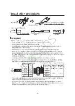
Evacute at the check valve of liquid stop valve and both sides of the gas stop valve. The oil
equalization pipe also must be vacuum (executed at the oil equalization pipe check valve
respectively).
Operation procedure:
Leakage test passed
Leave it for over 1
hour, vacuum pointer
does not arise.
After reaching -100.7KPa or
less (below -755mmHg), let
the vacuum pump running
continuously for over 1hour.
Charge refrigerant
Evacuation begins
Check vacuum
Evacuation ends
If vacuum pointer arises, it shows there is water or leakage in the
system, please check and modify it, and then evacuate again.

