


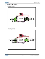


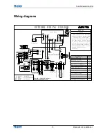


Wiring diagrams
Domestic air conditioner
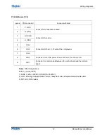
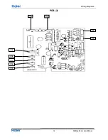
PCB (2) Module PCB
series
PCB connector
Connect with load
1 P
(CN1)
Connector for capacitance board
2 N
(CN5)
3 LO
(CN6)
Connector for reactor
4 LI
(CN7)
5 CN2
Connector for the U, V, W wire of the compressor
6 CN3
7 CN4
8
CN10
Connector for the DC power 5V and 15V form the control PCB
9 CN11
Connector for communicate between the control board and the module
board
Notes
: Other Designations
PCB (1) (Control PCB)
1) FUSE 1, (25A, 250VAC); FUSE 2(1A, 250VAC)
2) LED 1 Keep light representative normal, if keep flash interval representative trouble Alarm
3) RV1, RV2, RV3 Varistor
12


