background image

Connection to the Computer

The KE-USB36 attaches to your computer’s 
USB port. Use a standard A-B Male/Male 
type  USB  connecting  cable  from  the  KE-
USB36  to  the  USB  port  on  the  computer. 
The KE-USB36 may be connected directly 
to  the  USB  port  on  the  PC  or  through  a 
compliant USB Hub.

Connect the type “B” end of the USB cable 
into  the  KE-USB36  and  the  type  “A”  end 
into the PC or HUB USB connector.

The  KE-USB36  may  be  connected  to  the  computer  with  power 
on  or  off.  If  “hot  plugged,”  the  unit  will  generally  take  several 
seconds  to  become  fully 
active on your system.

Note:


The  first  time  you 

use  the  KE-USB36  with 
a  particular  PC,  you  will 
be  prompted  to  load  the 
appropriate  drivers  for  the 
device.  Follow  the  default 
selections  to  load  the 
standard drivers for the KE-
USB36.

The  KE-USB36  is  powered  directly  from  the  USB  port,  so  no 
external power is required.

The KE-USB36 is compatible with operating systems which offer 
full support for USB devices compliant to USB 1.0 specifications. 
Consult  the  operating  system  manufacturer  for  information  on 
device compatibility and downloads.

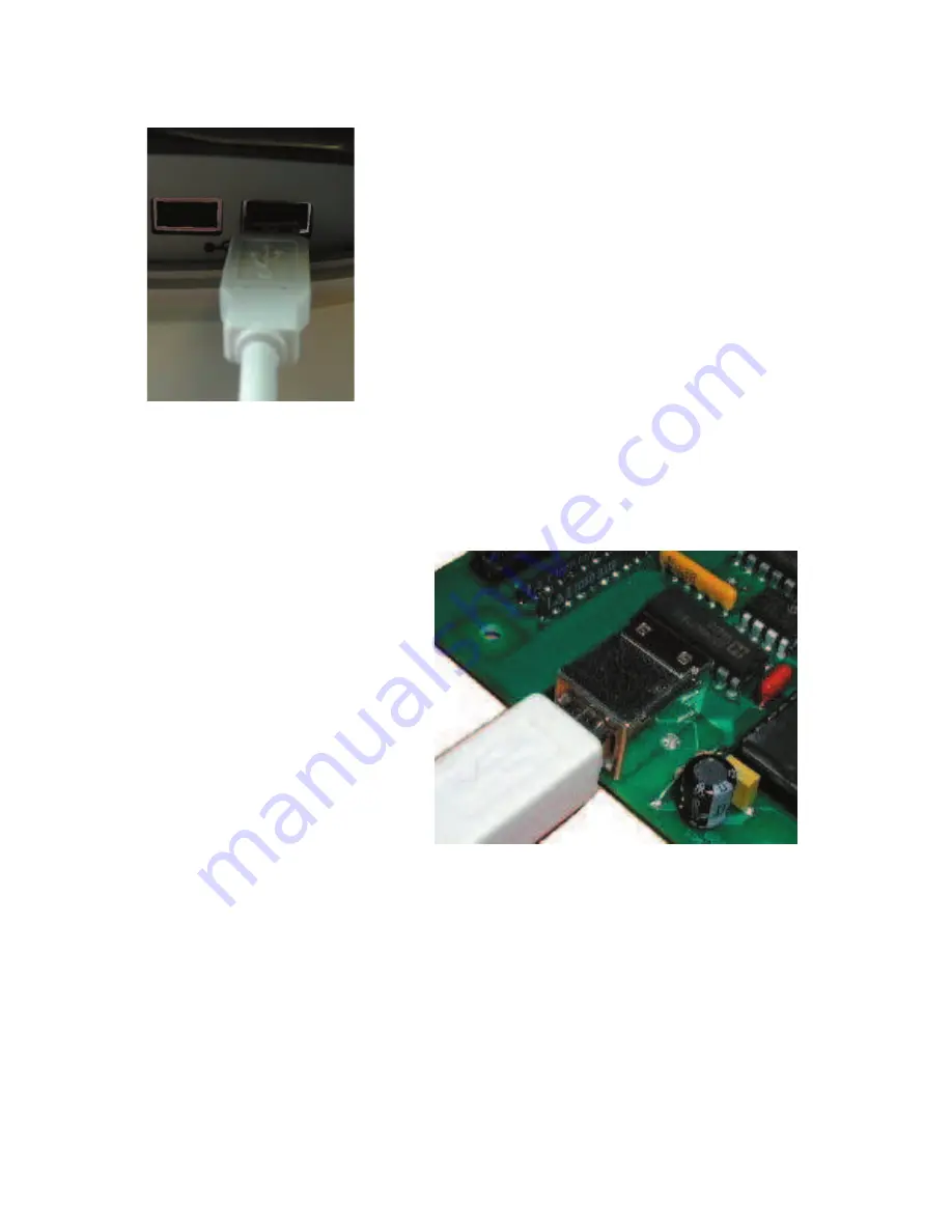
Figure 2

 - Connection of 

the USB cable to PC

Figure 3

 - Connection of the USB cable to 

KE-USB36

Appendix D:
Board ID

Two KE-USB36 devices may be connected to the same machine. 
Each KE-USB36 unit has a two position jumper which may be used 
to identify the unit as #0 (primary) or #1 (secondary). BoardID is 
0 or 1 based on the 2 position jumper setting on the board. ID 0 
= Jumper Open (default).  This jumper is located near the middle 
of the KE-USB36 board and is the only 2 position jumper on the 
unit (see figure 15).


5

16

Figure 15

 - Location of two position BoardID 

jumper.

Summary of Contents for KE-USB36

Page 1: ...KE USB36 PC Keyboard Encoder User Manual ...

Page 2: ... present on the unit Prudent handling and packaging is necessary to prevent damage to your computer Great care has been taken during the assembly testing and burn in of your KE USB36 to ensure its performance If you have any questions help is available Monday through Friday 8 00 am to 5 00 pm EST Toll Free 888 690 9080 or 540 465 4677 Your Keyboard Encoder is designed for OEM use and is not FCC pa...

Page 3: ...Input Header Keyboard Status Light Signals Interfacing to the KE USB36 Trackball Header Configuring the KE USB36 Appendix A Specifications Appendix B Operating Tips Appendix C KE USB36 Read Write from the Command Line Appendix D Board ID Accessories Custom KE USB36 Options 4 5 6 7 8 9 13 14 15 16 17 18 ...

Page 4: ...als received on this port are converted into mouse movement on the PC Note that you are not required to use both interfaces on the KE USB36 If you wish to use the device as a keyboard interface only do not attach to the trackball i n t e r f a c e connector If using the device as a trackball only do not program any inputs on the KE USB36 input header as keyboard keys you may still program inputs a...

Page 5: ...generally take several seconds to become fully active on your system Note The first time you use the KE USB36 with a particular PC you will be prompted to load the appropriate drivers for the device Follow the default selections to load the standard drivers for the KE USB36 The KE USB36 is powered directly from the USB port so no external power is required The KE USB36 is compatible with operating...

Page 6: ... to handle mechanical switch inputs and are debounced for that purpose Logic drivers may be attached to the inputs as well provided they are an active low logic level signal Refer to the Appendix A on specifications for the timing of logic signals Never attach any external power to the Inputs The KE USB36 input header is a dual row header with 100 spaced pins This format is suitable for many readi...

Page 7: ...d Cathode connections for these diodes are labeled on the board near the 6 pin LED header As with the input header this LED header is 100 spaced pins which is suitable for a variety of connectors Soldering to the pins is also an acceptable way to attach wires for connection to your LEDs The KE USB36 will drive on LED directly from each Anode Cathode pair of wires At 5 volts the drive current is ap...

Page 8: ...ckball header mates with the Hagstrom Electronics KE TBH3 interface cable see Accessories page of this manual In addition the user may create their own cable using the pin assignments as shown below Figure 7 The KE USB36 Trackball interface connector The connector features 8 pins spaced at 100 centers Figure 8 Trackball Interface signal assignments Note Do not supply any power into the Trackball i...

Page 9: ... box will then display the label for the key to which that particular input is assigned The scroll bar may be used to access the definitions for all 36 inputs of the KE USB36 Information pertaining to an input s keystroke definition is shown on each horizontal row To define a keystroke for an input simply move to the line that corresponds to the input number you wish to program and select the defi...

Page 10: ...use and the keyboard at all times If no Trackball device is connected to the unit no cursor movement will be initiated from the KE USB36 but the ability to emulate Left Middle or Right mouse buttons remains Any input defined as a keystroke may also be combined with a Ctrl Alt or Shift function or any combination of those three modifiers To initiate a Shift with the specified keystroke simply check...

Page 11: ...ram to program an input as one of these modifiers keys Control Alt or Shift If the input is to produce a repeated keystroke when held active the check box for the repeat function may be selected When active the repeat function will perform a repeat of the selected key exactly how your standard keyboard would handle a key held down The system settings dictate the repeat speed In addition to definin...

Page 12: ...pen selection and choosing a file from the selection list To save the configuration to the KE USB36 select File then Write to KEUSB36 Be sure that the KE USB36 is connected to the computer prior to this step Once loaded the new configuration will take effect on the KE USB36 The configuration is stored on the KE USB36 in non volatile memory Once a configuration is loaded into the unit it will remai...

Page 13: ...d connections 025 square pins spaced at 100 Required Input Current 1 2 ma sink current typical Input Active Time The input must be active for at least 20 msec to be considered valid 3 25 3 00 625 625 125 Dia 4 Note All dimensions are in inches 13 program window will display the device s current configuration Note Loading a configuration from the KE USB36 will overwrite any existing configuration s...

Page 14: ...hey do not drive voltage above the USB 5V supply on the unit The logic signals must produce an active logic low signal for the appropriate amount of time as listed in Appendix A The recommended maximum cable length from the KE USB36 input header to the input devices is 10 feet The recommended maximum cable length of the USB cable from the PC or Hub to the KE USB36 is 10 feet The Trackball header m...

Page 15: ...the Left and Right Shift Left and Right Alt Left and Right Control and Windows GUI keys can be used in addition to the six key limitation The KE USB36 has the option of repeating an input that is held on If the input is selected to repeat that input will count toward the six key limit Keys that are set to not produce a repeat will not be subject to the 6 key limitation provided there are no more t...

Page 16: ...osition jumper which may be used to identify the unit as 0 primary or 1 secondary BoardID is 0 or 1 based on the 2 position jumper setting on the board ID 0 Jumper Open default This jumper is located near the middle of the KE USB36 board and is the only 2 position jumper on the unit see figure 15 16 Figure 15 Location of two position BoardID jumper ...

Page 17: ...er several accessories to connect to your KE USB36 KE USBMM6 6 ft Male Male Type A to Type B USB Cable IOX36 Input Header to screw terminal breakout board This product connects to the KE USB36 input header through a standard IDE cable included Each input is brought out to a separate labeled screw terminal Use for solderless connection to the KE USB36 17 ...

Page 18: ...s just to name a few Give us a call to discuss your custom requirements Matrix Scanning Special Output Controls LCD Interface LED Interface Rotary Switch Inputs Serial Communication Alternate Function Keys Custom Machine Interfaces Questions or Comments Please give us a call Toll Free 888 690 9080 or visit us on the web www hagstromelectronics com email sales hagstromelectronics com In C In K In C...

Page 19: ...ending on the state in which you live you may have additional rights Great care has been taken during the assembly testing and burn in of your KE USB36 to ensure its performance If you have any questions please send us an email or give us a call Support is available Monday through Friday 8 00 am to 5 00 pm EST customer service email sales hagstromelectronics com Call Toll Free 888 690 9080 or 540 ...

Page 20: ...65 4677 Fax 540 465 4678 Monday through Friday 8 00 am to 5 00 pm EST sales hagstromelectronics com www hagstromelectronics com 1986 Junction Rd Strasburg VA 22657 Copyright 2017 HAGSTROM ELECTRONICS INC V 07 16 HAGSTROM ELECTRONICS INC ...

Reviews: