background image

0

Installation and Maintenance Manual, Compact CA

3.1.4a  Mounting the motor onto the driven shaft - shaft coupling

The motor can be mounted onto the driven shaft with or without a mounting tool, but the use of a 
mounting tool is recommended since it makes the work easier.
It is important to arrive at the correct clamping length between the driven shaft and the hollow 
shaft of the motor.
Ensure that the full clamping length is used by, for example, measuring and marking the driven 
shaft. This is of particular importance if the duty is so severe that a stress relieving groove has 
been made on the driven shaft. See Fig. 3.11, 3.11a and the table 3.8.

Mounting the motor with a mounting tool 

(Fig. 3.10)

 - Remove the End cover together with screws and washers.
- Align the motor with the driven shaft.
- Locate the existing plastic washer between the nut on the mounting tool and the bearingretainer. 

Pass the mounting tool through the centre of the motor, and screw it into the driven shaft to stated 
depth by using the key handle in the end of the tool.

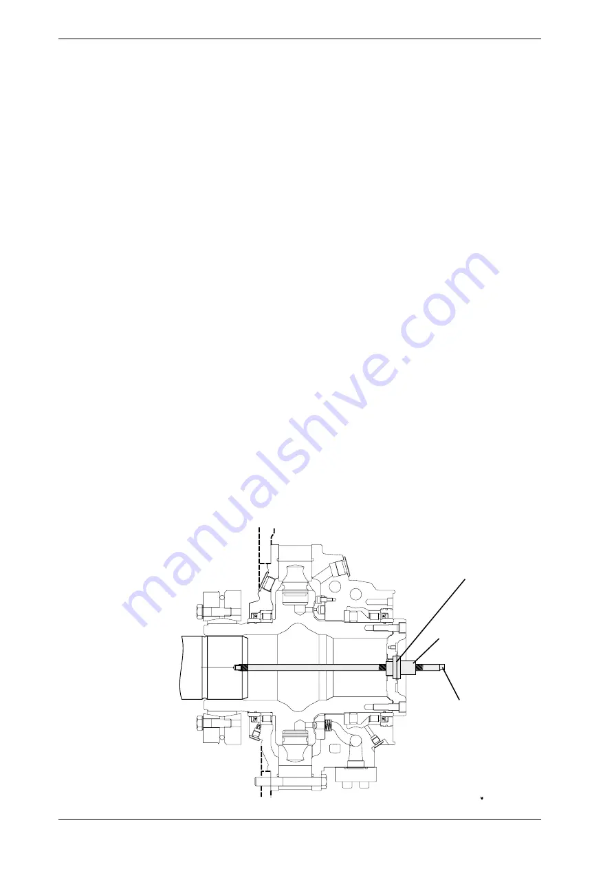
Fig. 3.10   Mounting the CA 50...210

1

1

1:1

Plastic Washer

Mounting tool

Nut

- Pull the motor onto the shaft by turning the nut on the mounting tool until the length  stated in the 

table 3.8,  is obtained; see Fig. 3.11.

- Tightening the shaft coupling see table 3.9
- Remove the mounting tool.
- Refit the plug.
- Refit the end cover and tighten the screws together with washers. Torque 81 Nm (59 lbf·ft).

Installation

Summary of Contents for Compact CA 100

Page 1: ...Installation and Maintenance Manual Compact CA EN411 13h 2006...

Page 2: ...nce accumulated over 30 years in marine and industrial areas Today this ongoing development work has resulted in the powerful COMPACT CA industrial motor New as well as established technical solutions...

Page 3: ...g the motor onto the driven shaft splines 22 3 1 5 Removing the motor from the driven shaft 24 3 1 6 Mounting the reaction point 25 3 1 7 Brake MDA 26 3 1 8 Brake MDA 5 7 10 26 3 1 9 Mounting MDA 5 7...

Page 4: ...the warning is ignored In this manual you will find the following signs which indicate a potential hazard which can or will cause personal enjury or substantial property damage Depending on the probab...

Page 5: ...5 350 400 350 CA 50 32 2010 32 280 400 350 CA 50 40 2512 40 230 350 350 CA 50 3140 50 200 280 350 1570 25 200 280 1 2 CA 70 40 2512 40 270 400 350 CA 70 50 3140 50 225 320 350 1570 25 225 320 1 2 CA 7...

Page 6: ...ystem Oil main lines are connected to ports A and C in the connection block and drain lines to ports D1 D2 or D3 in the motor housing The motor is connected to the shaft of the driven machine through...

Page 7: ...reased accordingly The graph is valid when 4 ports are used Max casing pressure is 3 bar 43 5 psi for 1 of the operation time evenly divided pressure peaks of max 5 seconds upto 8 bar 116 psi is allow...

Page 8: ...tion or casing This may well be the most important factor to consider since many structures may give rise to resonance resulting in severe noise problems Remarks Background noise The background noise...

Page 9: ...be contacted for approval in the case of these types of fluids RECOMMENDED VISCOSITY AT OPERATING TEMPERATURE 40 150 cSt 187 720 SSU FOR SPEED BELOW 5 RPM COATED PISTONS OR HIGH VISCOSITY SHALL BE USE...

Page 10: ...the drive as mineral oil Technical data Filtration The oil in a hydraulic system must always be filtered and also the oil from your supplier has to be filtered when adding it to the system The grade...

Page 11: ...the shaft in the horizontal plane the drain ports must be positioned vertically The higher of the two drain ports must be used see fig 3 25 When the motor is mounted with the shaft in the vertical pla...

Page 12: ...here is no radial or axial force on the shaft the shaft can be oiled only For production of the shaft see 278 2230 278 2231 278 2232 278 2233 278 2234 278 2235 278 2236 278 2238 and 278 2239 For contr...

Page 13: ...re where the centre of gravity is before any lifting Never stand below a hanging mo tor or torque arm Fig 3 4d CA 210 Steel eye with bolt Steel eye bolts 3xM12 Fig 3 4c Note The End cover and screws m...

Page 14: ...50 SA0N 205 2972 240 429 944 456 1003 CA70 XB0NH TA7 CA70 SA0N 175 2538 462 1016 489 1076 CA100 XB0NH TA5 CA50 SA0N 325 4712 270 489 1076 534 1175 49000 36100 CA100 XB0NH TA7 CA70 SA0N 290 4205 522 11...

Page 15: ...he end face of the hollow shaft when the coupling is fitted since this may cause damage to the coupling When in storage the motor must always be placed on the end face to the hollow shaft It is also a...

Page 16: ...screws the following must be observed Keep tension in your lifting wires to avoid a skew setting of the motor on the shaft during the tightening of the screws Wobbling caused by a skew setting of the...

Page 17: ...material and dimension on the driven shaft The conical surface between the coupling ring and the clamping rings the bolts shall be coated with MoS2 Molycote see Fig 3 8 This is done from the factory...

Page 18: ...the right direction when the motor is mounted in place on the machine To achieve the highest possible oil level in the motor housing the motor must be turned until the drain outlets are positioned ac...

Page 19: ...wards and on the right hand viewed from the motors main connection side Cylinders oil connection A B and C must point in the direction to the motor Mount the hoses The hose mounted to the high pressur...

Page 20: ...3 11 3 11a and the table 3 8 Mounting the motor with a mounting tool Fig 3 10 Remove the End cover together with screws and washers Align the motor with the driven shaft Locate the existing plastic w...

Page 21: ...Mounting the motor with a mounting tool Align the motor with the driven shaft using an overhead crane or lifting truck and press it carefully onto the shaft so that the length stated in the table besi...

Page 22: ...used Note 3 Tightening torque value is critical Use calibrated torque wrench Fig 3 14 Fig 3 14a Clean the driven shaft and the inside of the motor hollow shaft Fig 3 13 Installation Table 3 9 Motor t...

Page 23: ...plug Torque the G1 plug MV 125 Nm 90 lbf ft Mount the cover MV 81 Nm 59 lbf ft Oil to be filled before tightening bolt M20 L 100 mm Mounting kit 478 3629 801 Torquearm mounted motors Motors that carr...

Page 24: ...m 280 lbf ft Mount the brake according to 3 1 9 Torquearm mounted motors with brake o ring Installation Motors with brake BICA must have the screwed center cover disassembled See Installation and Main...

Page 25: ...g retainer torque 136 Nm 100 lbf ft and End cover torque 81 Nm 59 lbf ft as before Before dismounting the motor from the driven shaft the oil in the motor housing must be drained through the lower dra...

Page 26: ...ig 3 16 Mounting of pivoted attachment x 2 mm 0 079 misalignment in installation x 15 mm 0 59 movement when in use Bearing fitted with Loc Tite 601 Installation Fig 3 18 Alternative position Steel EN...

Page 27: ...with AW additives See diagram 3 1 on page 27 High pressure reduce service life for seals and axial bearing The brakes are fatigue resistant for a braking force corresponding to 67 of braking torque Th...

Page 28: ...cover 314 The springs shall be mounted against each other on the inner diameter 7 Mount the Brake cover 314 on the brake Oil the screws and assemble the screws Start mounting by slightly tightening th...

Page 29: ...sing the screw Fig 3 22 Installation Note The M12 screw can not be used to hold the Brake cover 314 while remo ving the screws 40 There is a risk that the threaded part in the Brake piston 313 can fai...

Page 30: ...x external load 200 kN 44800 lbf External load 110 kN 24600 lbf according to FEM M5 L2 T5 B1 B2 B1 and B2 Brake Motor Braking torque Begins to open at Fully open at Rec opening pressure Displ Max allo...

Page 31: ...th SPECIAL brakes may have different working operation Please make sure that you check the Ordering code on your brake The Diagram 3 2 shows the falling static braking torque 95 000 Nm 70 000 lbf ft M...

Page 32: ...r an equivalent grease without solid additives and mount the piston 313 Please read this in struction carefully before starting the disassembly 8 Grease the springs 315 with Texaco Multifak EP2 or an...

Page 33: ...directions shown by arrows R motor rotates clockwise and L motor counter clockwise wiewed from the motor shaft side If the motor is working in half displacement and in not prefered direction of rotati...

Page 34: ...Connections for 2 speed valve See fig 3 25b C A D y D1 C1 F3 F4 A1 T x Connection Description Remarks C1 C2 Main connection If C is used as the inlet the motor shaft rotates clockwise viewed from the...

Page 35: ...35 Installation and Maintenance Manual Compact CA Main connection A C Table 3 11 Drain connection D1 D2 Test connection T Installation Motor a mm in b c mm in CA 50 210 31 1 22 1 2 UNC 25 0 98...

Page 36: ...the motor and the oil supply connected to P give a counter clockwise rotation direction on a motor sign marked L as shown at fig 3 27 and fig 3 27b If the motor sign is marked R the motor rotation di...

Page 37: ...ntal plane it can be drained without special provisions for venting The highest of the three drain outlets D1 D2 or D3 must always be used see Fig 3 28 Drain line must be connected direct to the tank...

Page 38: ...ed in the normal drainline See 3 2 2 Connect the input line for flushing in the lowest flushing F3 or F4 see fig 4 1 For shaft pointing downwards input line shall be D3 see fig 3 29 When there is risk...

Page 39: ...e to ensure that no contamination enters the motor Seal connections A and C with the cover plate fitted to the connection surface at delivery Check that the O rings or rubber seals are in postion in t...

Page 40: ...the equipment and the type of duty This periodic maintenance must include the following operations Check the hydraulic system for leakage Tighten the screws replace faulty seals and keep the drive cle...

Page 41: ...low initially and increases rapidly later A sharp increase by a factor of 2 and 3 in the neutralisation number between inspections is a signal that the oil has oxidized too much and should be replaced...

Page 42: ...on the charge pressure side of the motor in the closed loop system Never out of the tank using the ball valves Clean the coupling and the hose carefully Connect the mini mess hose to the coupling but...

Page 43: ...f the motor The D connection Motor rotates in wrong direction Oil supply connections to motor incorrectly connected Connect the oil supply correctly Motor runs jerkily Pressure or flow fluctuations in...

Page 44: ...r under 3 3 10 13 Drain ing of brake cylinder Control of braking torque ac cording to 3 1 14 Dismantle the brake and replace the worn discs The brake does not open Insufficient brake opening pres sure...

Page 45: ...of conformity DECLARATION OF CONFORMITY The DECLARATION OF CONFORMITY above is available on request for deliveries from H gglunds Drives AB Translations into other languages are also available Example...

Reviews: