background image

Page 3

For internal use only

Assembly Instructions CB 280

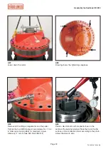
Grind the cam ring surface 
around the roll pin holes with 
a fi ne grinding stone.


It is very important to 

clean the cam ring good 

before assembling! 

Grind the spacer ring over the 
roll pin holes with a fine grind-
ing stone on both sides of the 
spacer ring. Do not grind on the 
sliding surface for the roller.

The highest cleanliness

 of the motor parts and of the 

workplace are basics to ensure the smooth functioning 
of the hydraulic motor!

Make sure to minimise that contamination can enter 
into the motor during the assembling.

Ensure that you have cleaned all motor parts thoroughly, 
especially if you have re-machined, grinded or in some 
other way worked up the motor parts.

After final cleaning of the motor parts, don’t leave the 
parts too long before assembling.

When lubricating

•   always use clean filtrated oil, recommended ISO class 
    16/13 according to ISO 4406, NAS.7,
•   always use clean grease of type Texaco Multifac EP2 
 or 

equivalent.

Rust protection

Use Shell Ensis SX or equivalent rust protection fluid.

Always use new gasket set.

Sliding surface

Important preparation before assembly

Work to be done before 
cleaning the motor parts:

Always treat the sliding 
surfaces with care

Shaft end housing

Connection block and valve plate

Summary of Contents for CB 280

Page 1: ...nstructions Compact CB 280 H gglunds Drives AB SE 890 42 Mellansel Sweden Tel 46 0 660 870 00 E mail aftersales se hagglunds com www hagglunds com This material is strictly for internal use within the...

Page 2: ...s to ensure the smooth functioning of the hydraulic motor A lifting capacity of 800 kg 1764 lb is required to perform this work Make a note in the service inspection report the motor type and individu...

Page 3: ...ter into the motor during the assembling Ensure that you have cleaned all motor parts thoroughly especially if you have re machined grinded or in some other way worked up the motor parts After final c...

Page 4: ...Note This orifice is only used when flushing of the seal is needed normally plugged A2 Install the flushing connection plug F1 G 1 4 Allen key 6 mm torque 30 Nm 22 lbf ft A4 Drawing shows the directio...

Page 5: ...the shaft end housing on supports x3 Equally devided Tool D 30205 A7 Tap down the radial lip seal turn the seal according to drawing A4 Tool D 30204 Note Be careful not to damage the seal lip A8 Lubri...

Page 6: ...t on the motor works as a frictional connection so no oil are allowed on the surface A11 Heat up the roller bearing to 110 C 230 F in an oven Tap the bearing down with a brass or a plastic rod The bea...

Page 7: ...aft Tap it down with a plastic hammer A15 Gently pull back the wear ring so that the lock ring no longer is loose To keep the lock ring permanent the wear ring has to be kept in place against the lock...

Page 8: ...The direction of the piston ring is important A18 Install the piston ring on the pistons Note Turn the piston ring according to drawing A17 A19 Lubricate the piston bores with oil Note Oil cleanlines...

Page 9: ...roller on top of the O ring to avoid damages to the sliding surface A22 Install the cam rollers into the pistons Check so the cam rollers slide easily A24 Position of cam ring mark seal retainer and s...

Page 10: ...wo lifting eyes M16 Note Before you install the cam ring make sure that the surfaces between the cam ring and the shaft end housing is absolutely clean A26 Lubricate the holes for the balancing sleeve...

Page 11: ...locating bolt with thread locking Thread locking can also be made by use of middlestrong locking Loctite No 243 A29 Lubricate the holes in the valve plate with oil and install the balancing pistons No...

Page 12: ...oll pin holes should correspond to the threaded holes in the shaft end housing Note Make sure that the surfaces between the cam ring and connection block are absolutely clean Important Place the lifti...

Page 13: ...Note Cleanliness very important Make sure that the surfaces are absolutely clean A39 Position of the axial radial bearing See Service information No 8 A37 Lubricate the 2 roll pins and install them w...

Page 14: ...the assembly plate T 000043 on to the bearing Make sure to center the tool carefully attach the screws through the holes in the assembly plate and to the cylinder block Tighten the screws thoroughly...

Page 15: ...ith grease and install it A47 Install the wear ring Tap it down against the bearing Use a plastic hammer A46 Lubricate the O ring for the wear ring with oil and install it A45 Rotate the cylinder bloc...

Page 16: ...cylinder block according to the picture Tighten the retainer screws Allen key size 10 mm Torque 136 Nm 100 lbf ft A51 Install the G1 plug with a new O ring into the bearing retainer Allen key 17 mm To...

Page 17: ...ace a support for the puller on to the bearing retainer A54 Place and install the puller tool T 000022 Tighten the bearing to a torque of 160 180 Nm 118 133 lbf ft A55 Lift up the motor slightly from...

Page 18: ...g retainer Place the tip on the flat surface on the connection block according to the photo Adjust the clock to zero A59 Remove all the lifting arrangements and the puller Tighten the four M20 Hexagon...

Page 19: ...n the screws and make the adjustment once again from A52 A62 The drawing shows the correct position of the seal A64 Install the radial lip seal into the seal retainer and tap it down with a plastic ha...

Page 20: ...s CB 280 A67 Protect the surfaces against rust Use Shell Ensis SX or equivalent rust protection fluid A68 Install the seal retainer A66 Install the O ring into the seal retainer A65 Lubricate the radi...

Page 21: ...ten the screws Allen key 10 mm Torque 136 Nm 100 lbf ft A72 Install the end cover lubricate and install the screws and washers Spanner size 18 mm Torque 80 Nm 59 lbf ft A71 Protect the surfaces agains...

Page 22: ...bf ft and all the drain connection plugs 1 torque 180 Nm 133 lbf ft A76 Seal the roll pins bores with the rubber plugs A74 Install the two plugs Torque 50 Nm 37 lbf ft A73 Lubricate with grease and fi...

Page 23: ...80 A77 Install the three test connections Torque 30 Nm 22 lbf ft A78 Install the M20 plugs x4 covering the FRP holes at the shaft end Allen key 10 mm Torque 50 Nm 37 lbf ft A79 Install the remaining c...

Reviews: