background image

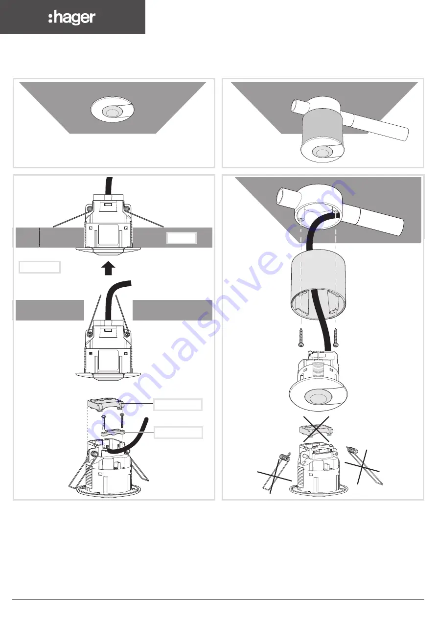
Mounting EEK510B

Surface mounting (with accessory EEK005)

1. Mount the BESA Box.

2.  Screw the accessory on the BESA Box.

3.  Remove the protective cover and the springs from the detector.

4.  Wire the detector according to the recommended connection diagram.

5.  Push and turn the detector to lock it into the accessory.

6.  Open the slider to set the potentiometers according to the desired values.

Ceiling mounting

1.  Cut out a 60 - 63 mm diameter hole using a hole saw. 

2.   Fix the detector by pushing both springs upward then insert them into the 

hole.

3.  Wire the detector according to the recommended connection diagram or 

plug into the klik.system marshalling box.

4.  Mount the protective cover over the terminals and screw the cable clamp.

5.  Set potentiometers according to the desired values.

5   < e <   20 mm

10   < t <   28 mm

10   < t <   28 mm

  5

10  < t <  28 mm

Ceiling 

t = thickness 

Protective  cover   

Cable clamp

2

1

3

6LE000505C

     Setting  instructions 

Summary of Contents for EEK51 P Series

Page 1: ...et the following features if the potentiometer is set on auto test Lux levels Time Absence presence detection Power up behaviour Active passive cell Override remote control The remote control EEK002 allows the switching ON or OFF of the light The EEK002 allows the same functionality as the wallswitch M M Detection areas h Y X Y X h x y 2 5 m 2 5 m 2 5 m 6 m 1 m Overlap Occupancy Sensors standalone...

Page 2: ...gramming tool EEK001 POWER UP state ON the light is immediately switched on for 30s after power up In case of detection the light in automatic mode remains on during the time delay otherwise the light is switched off OFF the detector switches to the selected mode after warm up Active passive cell Active cell The photocell will inhibit the output from the sensor if the ambient light level is suffic...

Page 3: ...e potentiometers according to the desired values Ceiling mounting 1 Cut out a 60 63mm diameter hole using a hole saw 2 Fix the detector by pushing both springs upward then insert them into the hole 3 Wire the detector according to the recommended connection diagram or plug into the klik system marshalling box 4 Mount the protective cover over the terminals and screw the cable clamp 5 Set potentiom...

Page 4: ...llation distance from ground 2 5m 3 5m In offices the detector must be installed above the workstation When associating several detectors detection areas shall overlap Keep away from environmental disturbances heat sources partitions houseplants ventilation da white da orange black Normally open retractive switch Polarity free digital output blue brown Live 230 V 50Hz supply Neutral L Connection t...

Reviews: