


I-LS02110
www.hagerco.com
10
Rev 2, 8/16
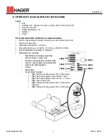
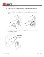
8.
Install (f) interior lever
9.
READ THE CODE USER MANUAL BEFORE BEGINNING OPERATIONS.
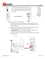
a.
Install four AA alkaline batteries in the (i) battery compartment
b.
Install (g) battery cover using (h) M5 x 10mm screw previously removed in step 4
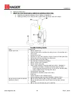
Troubleshooting Guide
Issue
Possible Fixes
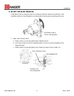
Interior Lever Rubs
Remove interior lever
Loosen all three interior escutcheon mounting screws so the escutcheon can
move around
Reinstall interior lever
Push down on lever until it bottoms out (end of travel) and hold against stop
Tighten down all three escutcheon mounting screws
Move lever back up to home position
See where lever is rubbing on escutcheon
Remove interior lever & escutcheon
Remove interior spring cage
Loosen interior escutcheon mounting plate (see Section F, Paragraph 5)
o
Shift plate in directions of binding (be careful to keep the Interior
Chassis Mounting Plate inside the cut out in the Interior Mounting Plate)
o
Hold and tighten Interior Mounting Plate screws
Reinstall Interior Spring Cage
Reinstall Interior Escutcheon (leave screws loose)
Install lever
Position escutcheon to be centered on lever
Tighten mounting screws and check for binding in motion of lever
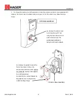
Chassis Does Not Install into External
Escutcheon (Step F)
Make sure removable mounting posts are fully seated in position
Make sure spindle grooves line up with bosses in spring cage / external
escutcheon
Make sure cam and tail piece line up for installation
(h)
(g)
(i)
(f)