


I-LS02110
www.hagerco.com
9
Rev 2, 8/16
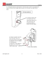
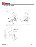
6.
Install interior rose assembly using two (SB1) M5 x 38mm screws, routing the wire as shown. Be
sure that the rose assembly is installed in the correct direction for the handing of the
door. The lever catch pin should be facing the latch edge of the door.
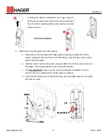
7.
Connect the cables to the inside of the (e) PCB while installing the interior housing. Install (c) the
interior housing assembly using three (d) M4 x 8mm screws previously removed in step 4.
(SB6)
(c)
(d)
(e)
Route Wire
Lever Catch /
Handing Pin
2P connector to power
cable (already
connected internally)
8P connector to main
cable
2P connector to lock
body cable
8P
2P


