ESEN-RMAR Installation, Commissioning & Operating Manual
Approved Document Ref: UI-ESEN-RMAR-01 Issue 5.0
12
INSTALLATION
CABLING
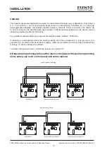
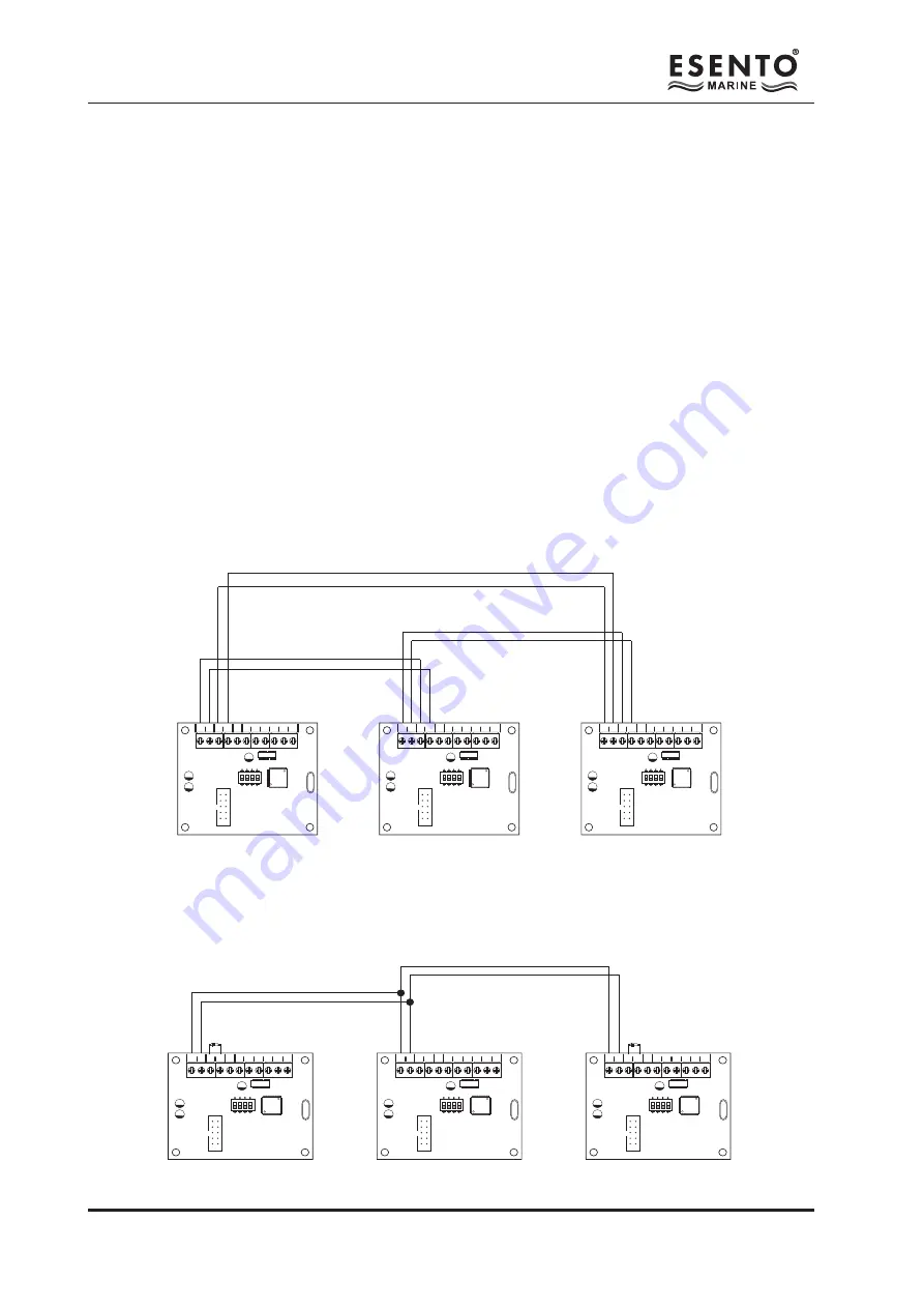
The repeater panels are designed to be wired in a fault tolerant (fail safe) loop configuration, from Comms
A +/- to Comms B +/- on the next repeater panel and so on until returning to Comms B +/- on the main
panel again (see diagram). This enables repeater panels to still work if there is a break in the cables. Up
to 1Km of cable can be used between each repeater. 120R terminating resistors can be used to reduce
interference between each leg of the loop.
Any suitable screened cable can be used or fire resistant cable, ‘NoBurn’, FP200 etc.
If replacing an older system where the existing cabling cannot be configured in a loop as shown, it is
possible to re-programme the panel back to legacy, radial circuit comms monitoring. This then allows any
topology of comms cabling to be utilised.
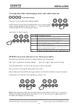
To change the repeater comms monitoring type see over (page 13).
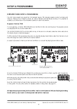
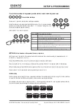
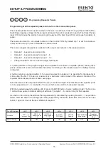
All repeater programming is done at the main control panel with Level 3 programming
mode active, see main control panel instruction manual.
COMS A COMS B 28
V+
SW -ve OUTPUTS
+ - + -
1
2
3
4
5
6
1
2
3
4
ON
ADDRESS
COMS A COMS B 28
V+
SW -ve OUTPUTS
+ - + -
1
2
3
4
5
6
1
2
3
4
ON
ADDRESS
COMS A COMS B 28
V+
SW -ve OUTPUTS
+ - + -
1
2
3
4
5
6
1
2
3
4
ON
ADDRESS
Fault Tolerant Loop Wiring
Main Panel
Repeater/Network Panel 1
Repeater/Network Panel 2
COMS A COMS B 28
V+
SW -ve OUTPUTS
+ - + -
1
2
3
4
5
6
1
2
3
4
ON
ADDRESS
COMS A COMS B 28
V+
SW -ve OUTPUTS
+ - + -
1
2
3
4
5
6
1
2
3
4
ON
ADDRESS
COMS A COMS B 28
V+
SW -ve OUTPUTS
+ - + -
1
2
3
4
5
6
1
2
3
4
ON
ADDRESS
Radial/Legacy Wiring
Main Panel
Repeater/Network Panel 1
Repeater/Network Panel 2
120Ω
120Ω
Summary of Contents for ESENTO MARINE ESEN-R-12MAR
Page 24: ...www haes tech com ...


