background image


12 


5.52.189.00.01.05


12.2 

Checking the load chain 


CAUTION!


The load chain must be tested over its entire length! 
The measure  of the load chain must be carried out especially in the areas which are subject to the highest 
wear. Through the lifting movement, these are the contact points of the chain with sprocket wheel and 
deflection pulleys. 


acc. DIN 685-part 5 


L11 = pitch increase over 11 chain links 


L1   = pitch increase over 1 chain link 


Illustration 5 


dm= detected link diameter (d1+d2)/2 


Illustration 6 


Chain dimensions 


Table 1 

Dimensions 

mm 

Chain size 

3x9  4x12 4,2x12,2 5x15 5,6x15,8 5,6x17 6x18 6,3x19,1 

7,1x20,1 

L11  105,6 136,6 138,2 170,6 179,1 194,2 203,9 216,4 227,9 

L1  9,9 12,7 12,8 15,7 16,6 18 18,9 20 21,2 

dm 2,7 3,6 3,8 21,2 5,0 5,0 5,4 5,7 6,4 


Table 2 

Dimensions 

mm 

Chain size 

7,1x21 7,9x23 8x24 9x24,8 9x27 10x28,1 10x30 13x36 16x45 

L11  238,5 260,6 272,1 281,2 300,8 318,6 340,7 408,3 505,6 

L1  22,3 24,1 25,3 26,1 28,1 29,6 31,8 37,9 47,4 

dm 6,4 7,1 7,2 8,1 8,2 9,0 9,0 11,9 14,4 


WARNING!


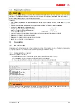
When the dimensions listed in the table are reached due to wear or deformation, the chain must be 
replaced! 


12.3 

Checking the load hook 

Load hook 
 
X = measuring distance hook mouth width 
Y = measured length from hook no. 6 
H = thickness of hook saddle 


Illustration 7 


Table 1 

Dimensions 

mm 

Capacity/chain falls 

0,25t/1 0,5t/1  1t/1  1,5t/1  2t/2  3t/2  5t/2 

or 

Y 28/38,4 28/38,4 32/43,4 36/48,9 40/55,4 44/63,6 50/74,8 

H  19,3 19,3 25,1 28,8 33,4 39,2 44,5 

Dimensions in the tables are theoretical values without tolerances. 


Please fill in the measured 
values before 
commissioning: 

Capacity t 

X  or Y 

mm 

H mm 


CAUTION!


When the dimension of hook opening width is deformed more than 10% or when the dimension of the hook 
bottom thickness is fallen short of by 5% due to wear, the hook must be replaced. 


Summary of Contents for 11/09

Page 1: ...5 52 189 00 01 05 Rev 05 HADEF Aluminium Spur Gear Chain Hoist Type 11 09 Installation Operating and Maintenance Instructions ...

Page 2: ... Subject to changes Table of Contents 1 Information 3 2 Safety 4 2 1 Warning notice and symbols 4 2 2 Duty of care of the owner 4 2 3 Requirements for the operating personnel 5 2 4 Appropriate use 5 2 5 Basic safety measures 5 3 Transport and Storage 6 3 1 Transport 6 3 2 Safety device for transport 7 3 3 Storage 7 4 Description 7 4 1 Areas of application 7 4 2 Design 7 4 3 Functions 7 4 4 Importa...

Page 3: ... a certified quality assurance system as per ISO 9001 The production of components at our work is subject to strict intermediate checks After assembly each product is subject to a final test with overload For the operation of hoists the national accident prevention regulations apply in Germany amongst others The stated performance of the devices and meeting any warranty claims require adherence to...

Page 4: ...or they must be suitable for use in area prone to explosion The owner is responsible for this However in everyday operation this degree of safety can only be achieved if all measures required are taken It falls within the duty of care of the owner user of the devices to plan these measures and to check that they are being complied with Complete the operating and installation instructions by any in...

Page 5: ...riginal spare parts must be used Non compliance will result in any warranty claims becoming void Liability and warranty will become void if unauthorized modifications of the units are made by the user The appropriate use of the hoists is vertical lifting and lowering of unguided loads In combination with trolleys loads can also be moved horizontally DANGER It is not allowed pulling loose of stuck ...

Page 6: ...Twisted chains must be aligned before attaching the load The correct alignment of the chain links can be seen from the weld seams The chain links must always be aligned in one direction Don t bump against something with load or hook Illustration 1 Motor drive is prohibited The devices are not suitable for continuous operation In order to avoid too high temperatures of the brake discs that are not ...

Page 7: ...t permitted to use the unit in an area at risk from explosion 4 2 Design Ratchet lever hoists are manual hoists with suspension hook for stationary use They can also be combined with monorail trolleys Operation by hand through hand chain Illustration 2 4 3 Functions The load is lifted or lowered by pulling one of the chain falls of the endless hand chain of the hoist A load pressure brake prevents...

Page 8: ...0 8 9 1 5 tion depends travel limit m that any ela oving gear e g fo ces securely ar with the o uthorized by nstructions a ling the endl t the right sid s clockwise all at the lift s s anti clockw is only made hain All com ttaching the ts the hoist b oad is stopp for the hook he bolt out e 500 1 5X15 940 210 8 9 1 5 s on the local must be place astic limitatio ork lift lifting operation of t the e...

Page 9: ...Inspections as above Please observe the national rules and regulations and the instructions in this manual NOTICE Hoists up to 1000 kg capacity and without motor driven trolleys of hoisting unit must be tested by a qualified person before putting into operation for the first time Hoists of 1000 kg capacity and up or with more than one motor driven hoist movement i e lifting and trolley movement mu...

Page 10: ...ing Trolley drive The open lying teeth of the trolley drive must be lubricated Hand gear for hand geared trolley Ensure correct fit of the hand chain it must not be twisted and must hang freely 10 2 Functional test Lifting gear Check lifting and lowering functions initially without a load Then check the brake function under load The load must be securely held Trolleys Carefully move the trolley to...

Page 11: ... yearly by a qualified person or licensed qualified person regarding its functional safety 12 1 1 Components to be checked The following must be checked Dimensions of load chain load hooks pawls bolts ratchet wheels brake linings The dimensions must be compared to the dimensions in the tables A visual inspection for deformations cracks and corrosion must be carried out at commissioning daily check...

Page 12: ...x21 7 9x23 8x24 9x24 8 9x27 10x28 1 10x30 13x36 16x45 L11 238 5 260 6 272 1 281 2 300 8 318 6 340 7 408 3 505 6 L1 22 3 24 1 25 3 26 1 28 1 29 6 31 8 37 9 47 4 dm 6 4 7 1 7 2 8 1 8 2 9 0 9 0 11 9 14 4 WARNING When the dimensions listed in the table are reached due to wear or deformation the chain must be replaced 12 3 Checking the load hook Load hook X measuring distance hook mouth width Y measure...

Page 13: ...depending on usage Lubricate the chain with oil that creeps Always lubricate the chain when it is not under load so that the oil can wet the links affected by wear It is not sufficient to lubricate the chain from the outside as this will not ensure the formation of a lubricating film within the links The adjacent link points must always be lubricated to prevent excessive wear If the same lifting o...

Page 14: ...ressure brake During the check brake lining wear is verified The brake linings must be replaced when the wear limit is already reached at one position of the lining as this can be the case when wear of the linings is irregular CAUTION The brake linings must be free from fracture Avoid oil grease dirt and humidity on the brake linings as this increases wear 13 6 Overload protection DANGER The facto...

Page 15: ...e brake linings Load chain is twisted Align the load chain Defect of chain gear or chain wheels Do maintenance and replace defective parts by original spare parts Pawl does not engage properly Check the pawl and replace it if necessary Pawl spring is missing Do maintenance and replace defective parts by original spare parts It is difficult to lift the load Overload reduce the load to nominal load ...

Page 16: ...decommissioning leaving plenty of space Read the chapter Safety instructions Disassembly is carried out in reverse order to the assembly Please make sure that all operating material is disposed of in accordance with environmental regulations 16 1 Temporary decommissioning Measures are as above Also read the chapter Transport and storage 16 2 Final decommissioning disposal Measures are as above Aft...

Reviews:

Related manuals for 11/09