Step 9: Frequency Modulation (FM) Receiver Kit
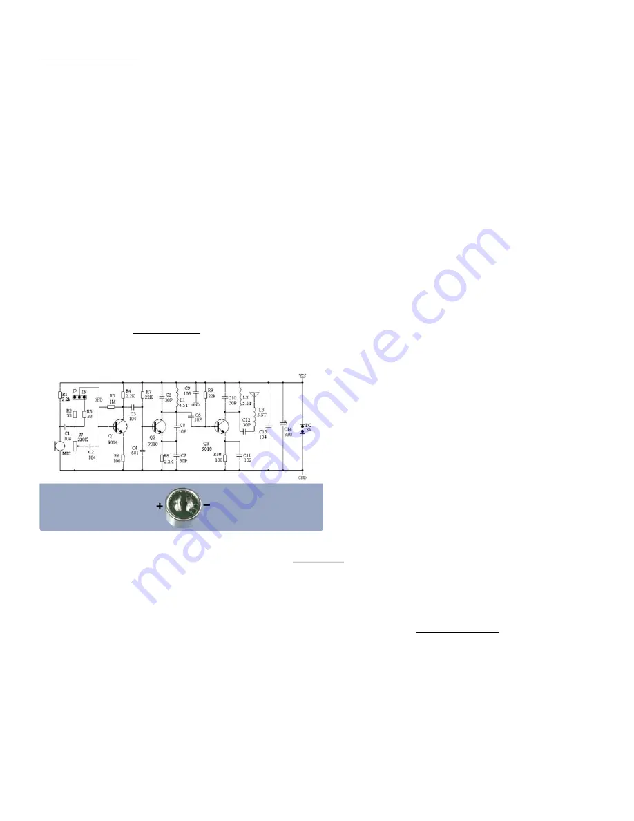
An input audio signal can be collected by the onboard
electret microphone or provided from another
electrical source into the input header pins. The
microphone leads can be extended using wire or
trimmed leads from other components to allow
connection to the PCB. The microphone lead
connected to the outer housing of the microphone is
the negative lead as shown in the image.
At transistor Q1, Frequency Modulation is achieved
when a carrier oscillator frequency is modi ed by the
audio signal. The trimmer potentiometer may be used
to adjust input attenuation of the audio signal. The
audio signal is coupled to the base of transistor Q1 via
C2.
Transistor Q2 (along with R7, R8, C4, C5, L1, C8, and
C7) provides the high frequency oscillator. C8 is the
feedback capacitor. C7 is the DC-blocking capacitor. C5
and L1 provide the resonant tank for the oscillator.
Changing the values of C5 and/or L1 will change the
transmit frequency. After initial assembly, the default
transmit frequency will be about 83MHz. Gently
spreading the turns of coil L1 a tiny bit will change
the value of the inductor L1 and shift the
transmission frequency accordingly. Keeping the
frequency around 88MHz-108MHz will allow the
signal to be received using any FM radio, including
the SDR receiver.
Transistor Q3 (along with R9, R10, L2, C10, and C1)
forms a high frequency power ampli er circuit. The
modulated signal is coupled to the amplifying circuit
through capacitor C6. C10 and L2 form an
ampli cation tuning tank. Maximum output power is
achieved when the ampli cation loop of C10 and L2
are tuned to the same frequency as the carrier
oscillator loop of C5 and L1.
Finally, C12 and L3 provide antenna turing where the
ampli ed signal is driven into a wire antenna for
transmission as radio frequency electromagnetic
waves.
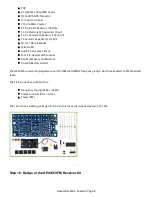
This FM receiver kit is based on the HEX3653 chip, which is a highly integrated FM Demodulator.
The kit includes:
HackerBox 0034: SubGHz: Page 7


