


34
Installation
3.9.4 Sensor removal
•
If not using the ORBISPHERE 32003 insertion/extraction valve (refer to
insertion/extraction valve on page 35
) you will need to shut off the sample flow and drain the
sampling circuit of liquid.
•
Remove the sensor cable connected at the sensor end.
•
Hold the sensor body in one hand to avoid rotation, and unscrew the collar with the other
hand.
•
Pull the sensor straight out of the socket or flow chamber.
•
Install sensor storage cap and sensor base (to protect the connection).
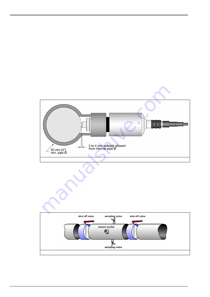
3.9.5 Weld-on stainless steel socket
The ORBISPHERE 29501 weld-on sensor socket can be used to install a sensor into a stainless
steel pipe (min.Ø 50 mm or 2”). When welding the socket to the pipe, check that setback
between the pipe’s inner diameter and the sensor tip does not exceed 4 mm (see diagram).
Note:
Be sure to remove the two O-rings from the socket before welding and leave the sensor’s stainless
steel cap screwed on during welding to prevent thread distortion.
Recommendation:
To facilitate sensor removal and installation, we suggest installing the socket in a location where
the liquid can be drained quickly and easily. By creating a one meter long piece of pipe (refer to
) with shut off valves at both ends, just a small volume of liquid needs to be drained to
enable sensor removal.
Also, a precise sensor and socket installation can be performed in the workshop, and this
assembly can be placed in the production line with minimal down time.
Figure 20 Weld-on sensor socket
Figure 21 Installation in-line
Summary of Contents for ORBISPHERE K-M1100
Page 5: ...4 Table of Contents ...
Page 19: ...18 Specifications ...
Page 39: ...38 Installation ...
Page 45: ...44 User Interface ...
Page 48: ...47 Section 6 View Menu Figure 33 View menu ...
Page 51: ...50 View Menu ...
Page 52: ...51 Section 7 Measurement Menu Figure 36 Measurement menu ...
Page 59: ...58 Measurement Menu ...
Page 65: ...64 Calibration Menu ...
Page 66: ...65 Section 9 Inputs Outputs Menu Figure 39 Inputs Outputs menu ...
Page 68: ...67 Inputs Outputs Menu 9 4 Analog outputs Figure 40 Analog outputs menu ...
Page 75: ...74 Inputs Outputs Menu ...
Page 91: ...90 Communication Menu ...
Page 94: ...93 Section 12 Products Menu Figure 43 Products menu ...
Page 97: ...96 Global Configuration Menu ...
Page 98: ...97 Section 14 Services Menu Figure 45 Services menu part 1 ...
Page 99: ...98 Services Menu Figure 46 Services menu part 2 ...
Page 107: ...106 Maintenance and Troubleshooting ...
Page 113: ...112 Accessories and Spare Parts ...


