background image

Page 17

51350-18 Aquatrend Interface Network.fm

Aquatrend

®

 Interface Network

Section 2

Aquatrend

®

 Interface Network

2.1 Network Description

This section describes requirements and options for setting up the AquaTrend 
Interface Network System. A “network” is the connection of one or more 
devices (of which at least one is a sensor) to a Master AquaTrend Interface. 
This Master AquaTrend Interface serves as the network control panel. 
Devices can include Signal Output Modules (SOM), Digital Display Modules 
(DDM), Serial I/O Modules (SIO), Remote AquaTrend Interfaces and 
Portable AquaTrend Interfaces.

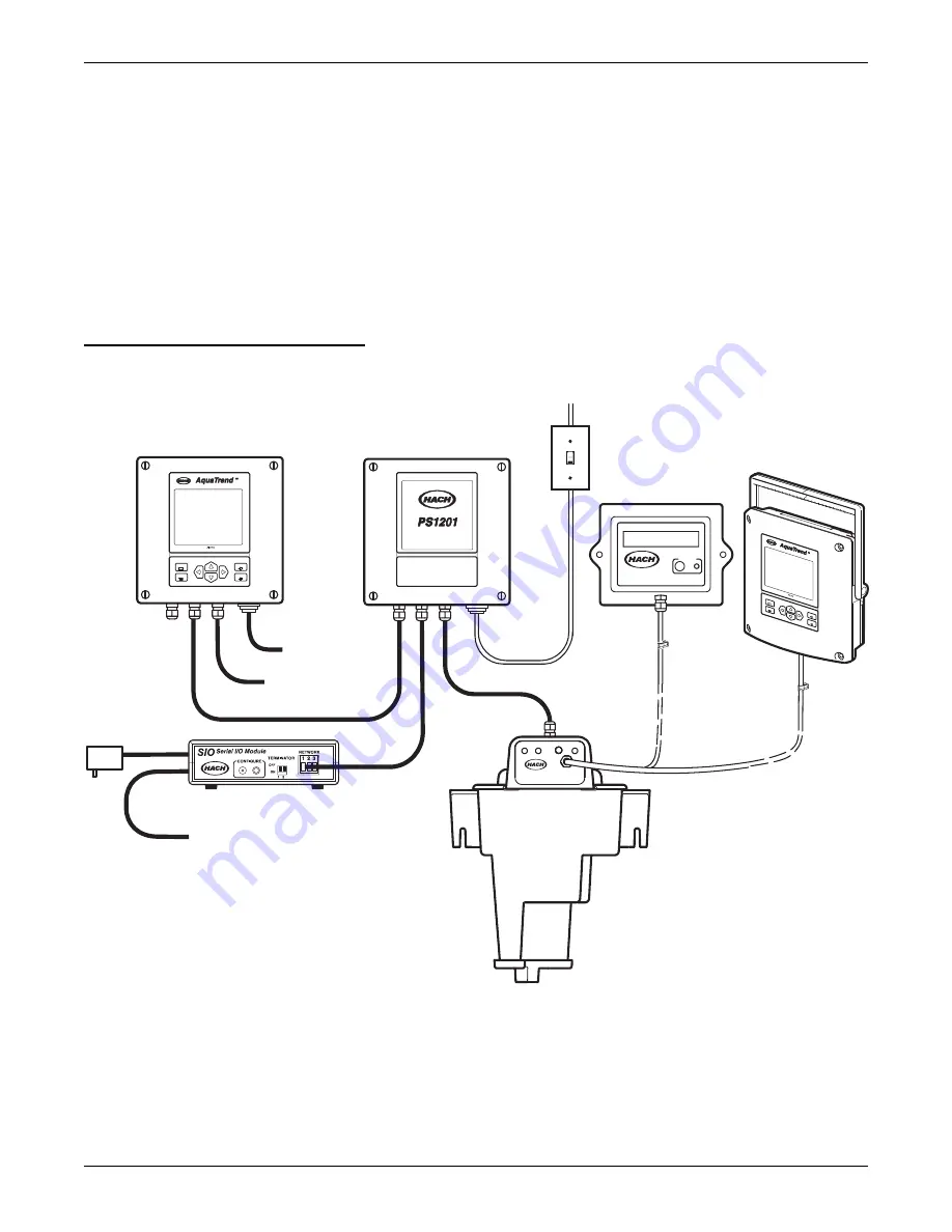
Figure 6

 shows an example of a single-sensor AquaTrend Interface Network 

System. An example of a multi-sensor system is shown in 

Figure 7

.

Figure 6

 Single-Sensor AquaTrend Interface Network

Each sensor (i.e., the 1720D Turbidimeter) manual provides instructions for 
setup of the single-sensor network. Each of the other device manuals, 
(AquaTrend/SOM, AquaTrend Interface, Digital Display Module, Serial I/O 
Module, Signal Input Module and Signal Output Module) provides setup 
instructions for their components. 

Section 2.3

 describes the maximum 

number of devices that can be managed by one Master AquaTrend Interface 
on a system. 

EXIT

ENTER

MENU

DISPLAY

EXIT

ENTE

R

MEN

U

DISP

LAY

Power Supply 12V DC

Network Connection Module

DIGITAL
DISPLAY MODULE

CONFIGURE

ON

OFF

1720D

AC Power

4-20mA Outputs

RS232 Computer or Printer Interface

Relays

115 / 230 VAC
Power In

Either the

DDM or the

Portable AquaTrend

Customer Supplied
ON/OFF Switch

Spare -

open for

expansion

Summary of Contents for AquaTrend 51200

Page 1: ...g Number 51350 18 AquaTrend Interface Model 51200 AquaTrend Model 51350 AquaTrend SOM Model 51400 Portable AquaTrend Instrument Manual Hach Company 2001 2002 All rights reserved Printed in the U S A 11 02 6ed ...

Page 2: ...aTrend SOM with Integrated Signal Output Module 18 2 2 3 Portable AquaTrend Interface Module 19 2 2 4 Sensor 19 2 2 5 Signal Output Module SOM 19 2 2 6 Signal Input Module 19 2 2 7 Serial I O Module SIO 19 2 2 8 Digital Display Module DDM 20 2 2 9 Repeater Module 20 2 3 Network Design 20 Section 3 Initial AquaTrend Setup 23 3 1 Identifying the Master AquaTrend 23 3 1 1 Adding Remote AquaTrend Inte...

Page 3: ...3 4 1 Alarm to Relay Connections 43 4 1 1 Setting Alarm Parameters 43 4 1 2 Attaching an Alarm to a Relay 43 4 1 3 Detaching an Alarm from a Relay 44 4 1 4 Connecting a Recorder Signal to an Output Device 45 4 1 5 Detaching Recorder from Analog Output 46 4 2 Alarm Log 47 Installation and Maintenance 49 Section 5 Hardware Installation 51 5 1 Mounting Instructions for the AquaTrend Interface 51 5 1 ...

Page 4: ...ard Test 71 6 2 3 Memory Test 71 6 2 4 Verify Program Checksum 72 6 2 5 Clear Alarm Log 72 6 2 6 AquaTrend Interface Cold Start 72 6 2 7 Service Menu 73 6 3 Network Diagnostics 73 6 3 1 Print Network Image 73 6 3 2 Query Device Status 73 6 3 3 Test for Duplicate or Wrong Node 73 6 4 Troubleshooting 74 Glossary 81 General Information 85 Replacement Parts and Accessories 86 How to Order 87 Repair Se...

Page 5: ...Page 5 51350 18 safety page fm Safety Precautions Safety Precautions Section 5 3 1 AquaTrend Interface with Signal Output Module SOM to PS1201 Power Supply Connections on page 60 ...

Page 6: ...uts isolated to 500 VDC may be trimmed 20 if needed via AquaTrend Interface Relays AquaTrend with SOM only SPDT 250 VAC 5A resistive Communications Echelon fieldbus compatible utilizes LonTalk protocol Maximum of 400 meters between devices with a 500 meter maximum per segment distances in excess of 500 meters require a repeater Up to 3 repeaters can be used for a total network length of 2000 meter...

Page 7: ...Page 7 51350 18 operation stopper fm Operation Operation ...

Page 8: ...Visit http www hach com ...

Page 9: ... Interface After adding all devices to the network you must designate which devices communicate with one another For example once a sensor is attached to an AquaTrend Interface you must instruct the sensor to attach its reading to a designated AquaTrend Interface display channel Because many underlying network connections occur when performing network operations it is important to have all existin...

Page 10: ...le damage has occurred during shipment Contact Hach Customer Service at 1 800 227 4224 if any items are missing or damaged Refer to Safety Precautions on page 5 and to the sections referenced on that page Section 5 of this manual See the Quick Reference Guide and section 3 1 1 on page 23 of this manual Section 3 and Section 4 of this manual Table 1 Items Packaged with AquaTrend Interface and AquaT...

Page 11: ...s a link between sensors and communication devices This networked system provides simplified use of multiple instruments and requires fewer wiring configurations than systems without a single digital wiring bus The AquaTrend Interface is available in three different physical configurations AquaTrend Interface AquaTrend Interface with SOM Portable AquaTrend Interface See section 2 2 Device Descript...

Page 12: ...ories with summaries of the arrow key functions for each screen category Table 3 AquaTrend Interface Key Functions Number Key Function of Keys 1 Allows you to navigate through the various menus to change settings and to move the cursor when observing graph data Table 4 summarizes the functions of the arrow keys in each menu view 2 Displays active data in numeric or graphical format Pressing the DI...

Page 13: ... are attached to separate channels labeled A P on the AquaTrend Interface Refer to Figure 4 and Figure 5 for descriptions of each field Figure 3 AquaTrend Interface Display Categories Table 4 Arrow Key Functions Screen Category Function 1 Menu Screen Move the pointer to next down or previous up item For menus no longer than one page the pointer will loop around from the bottom to the top or from t...

Page 14: ... here 3 Date Current date 4 Alarms Numbers that appear here 1 through 8 correspond to the sensor with active alarms If N appears in this field a Network alarm is active If no indicators appear in this field no system alarm is active See section 4 2 on page 47 for information on reviewing alarms 5 Security Icon When displayed indicates a security level of Partial or Total Hourglass Icon When displa...

Page 15: ...ata If data is being reviewed in the 24 hour or 30 day mode this field is replaced with the date 8 Cursor Time Date Time or date value of data at cursor position 9 Graph time X axis upper limit Current time latest data If data is being reviewed in the 24 hour or 30 day mode this field is replaced with the date 10 Graph Cursor Retrieves value of data at cursor position 11 Graph Area Graph of 60 min...

Page 16: ...king with Since all of these menu items are stored within the sensor they are designed to be sensor specific Access this menu to change sensor settings or information 1 5 4 Other Device Menu The other device menu contains information specific to accessory devices that are not sensors Such examples include Signal Output Modules Serial I O Modules and Digital Display Modules Access this menu to chan...

Page 17: ... An example of a multi sensor system is shown in Figure 7 Figure 6 Single Sensor AquaTrend Interface Network Each sensor i e the 1720D Turbidimeter manual provides instructions for setup of the single sensor network Each of the other device manuals AquaTrend SOM AquaTrend Interface Digital Display Module Serial I O Module Signal Input Module and Signal Output Module provides setup instructions for...

Page 18: ...ices Portable AquaTrend Interface Mobile device designed for set up and calibration of sensors already on the network Portable AquaTrend Interfaces can communicate with one sensor at a time and cannot perform network operations See section 2 2 3 and 5 2 for more information about the Portable AquaTrend Interface All AquaTrend Interfaces have the capability of functioning as a Master or Remote howe...

Page 19: ...keypad at either 4 20 or 0 20 mA Signal Output Module functionality can be provided either in an AquaTrend SOM or in a separate Signal Output Module See the Signal Output Module Manual for detailed information 2 2 6 Signal Input Module The Signal Input Module SIM is configured as a sensor on the network system and provides two 4 20mA analog inputs These inputs can be used to bring measurements fro...

Page 20: ...rements and menus but only the Master AquaTrend Interface can perform network operations through the Network Menu The system can contain as many as nine AquaTrend Interfaces but only one can be the Master AquaTrend Interface Each AquaTrend Interface is programmed in an undetermined state when shipped from the factory and must be designated as a Master or Remote when initially attached to the netwo...

Page 21: ...terface Devices Device Power Required watts AquaTrend SOM 5 AquaTrend Interface 2 Portable AquaTrend Interface 2 Digital Display Module DDM 2 Signal Output Module SOM 3 Signal Input Module SIM 2 Serial I O Module SIO Provides its own AC wall plug power supply 1720D Turbidimeter sensor See the 1720D Turbidimeter manual ...

Page 22: ...h Customer Supplied ON OFF Switch Relay Contacts Relay Contacts 4 20 mA Outputs 4 20 mA Outputs For Network Expansion For Network Expansion 1720D Network Communications Cable Power Supply 12V DC Power Supply 12V DC Network Connection Module Network Connection Module ON ON OFF OFF Signal Output Module EXIT ENTER MENU DISPLAY DIGITAL DISPLAY MODULE CONFIGURE DIGITAL DISPLAY MODULE CONFIGURE ...

Page 23: ...Network Manager to ON After a brief delay the display will show the data display screen CHANNEL NOT ASSIGNED 3 Press the Menu key to proceed to the Main Menu 3 1 1 Adding Remote AquaTrend Interfaces to the Network Upon power up new AquaTrend Interfaces on the network will search for a Master AquaTrend Interface The exception is when installing an AquaTrend Interface that has previously been instal...

Page 24: ...in the following sections 3 3 1 Setting the Time 1 Press the MENU key to access the Main Menu 2 Use the up or down arrow key to move the pointer to AquaTrend Menu and press ENTER 3 Select the SET TIME DATE option and press ENTER Note The AquaTrend Interface uses a 24 hour clock military time so there is no selection for a m and p m For example if the current time is 4 00 p m enter the 24 hour form...

Page 25: ...press ENTER to accept or press EXIT to cancel 3 3 3 Changing the Date Format a To change the date format select DATE FORMAT from within the Set Time Date Menu A pop up box will appear requesting SELECT DATE FORMAT b Select the preferred date format MM DD YY is month day year and DD MM YY is day month year 3 3 4 Setting the Correct Day of the Week The internal calendar programs the day of the week ...

Page 26: ...s an integral part of an AquaTrend Interface or as a separate device 1 SIO 1 DDM and 1 remote AquaTrend Interface During this procedure the default device settings are accepted and sensor measurements are automatically assigned to appropriate channels 1 Press the MENU key to access the Main Menu 2 Choose Network Menu 3 Select SINGLE SENSOR SYSTEM A pop up box will appear stating SINGLE SENSOR SYST...

Page 27: ...e selected automatically if two or more devices of the same type are available the AquaTrend Interface will ask you to press the configure button on the device you want to add 6 Press the configure button on the device to be added if necessary Refer to the device s manual if you do not know where to find its configure button 7 Select ADD DEVICE and press ENTER 8 The AquaTrend Interface will config...

Page 28: ...ystem this remove device software procedure must be performed This assures that all network communications associated with the device are properly removed to avoid miscommunication from other devices on the network Proceed as follows 1 Press the MENU key to access the Main Menu 2 Use the up or down arrow key to move the pointer to NETWORK MENU and press ENTER 3 Select REMOVE DEVICE and press ENTER...

Page 29: ...or replacement and press ENTER Or press the configure button on the device you want to replace press the ENTER key on a remote AquaTrend Interface If only one device to replace is available it will be selected automatically 6 A pop up box will appear showing the device to be replaced If it is correct choose REPLACE DEVICE 7 A warning pop up box will appear Select CONTINUE and press the ENTER to co...

Page 30: ...HANNEL and press ENTER 5 Select ATTACH and press ENTER A list of available sensors will appear 6 Select the sensor of interest and press ENTER 7 Select the channel of interest and press ENTER If the sensor has more than one measurement available select the desired measurement and press ENTER 8 Select ATTACH and press ENTER to continue or select Cancel to cancel the attachment The message OPERATION...

Page 31: ...e OPERATION COMPLETE will appear The screen will return to the display setup menu upon completion of the measurement to channel setup 3 5 Additional AquaTrend Interface Menu Features 3 5 1 Display Setup The DISPLAY SETUP menu lets you adjust the contrast setting and customize several display options 3 5 1 1 Contrast Adjustment 1 Press the MENU key to access the Main Menu 2 Select AQUATREND MENU an...

Page 32: ...isplay the data collected in graph form over the past 2 hours 8 hours 30 hours 7 days or 30 days Graph time appears on the x axis horizontal axis the range of recent sensor readings are shown on the y axis vertical axis The default graph time is 60 minutes for all channels Enable the graph cursor by pressing the ENTER key The cursor will appear in the center of the graph use the right and left arr...

Page 33: ...from a single sensor or from up to eight sensors at one time Viewing additional channels reduces the amount of information shown for each channel Access the display mode by pressing the DISPLAY key Use the right arrow key to increase the number of channels displayed on the screen Press the left arrow key to decrease the number of channels displayed The up and down arrow keys move the active channe...

Page 34: ...t password is HACH and the default security level is NONE A security level of NONE allows access to all functions 3 8 1 Setting the Password Enter a new four digit password as follows 1 Press the MENU key to access the Main Menu 2 Select the AquaTrend Menu option and press ENTER 3 Select SECURITY SETUP and press ENTER 4 Select SET PASSWORD and press ENTER 5 Use the arrow keys right or left arrows ...

Page 35: ...e but with no option to change settings except CONTRAST LEVEL without a password Change the security level as follows 1 Press the MENU key to access the Main Menu 2 Select AquaTrend Menu and press ENTER 3 Select SECURITY SETUP and press ENTER Move the pointer to SECURITY LEVEL and press ENTER 4 Use the arrow keys right or left arrows to move to another character space and the up or down arrows to ...

Page 36: ... pointer to the required unlock duration and press the ENTER key To cancel temporary unlock perform steps 1 5 and select CANCEL TEMP UNLOCK and press ENTER When the temp unlock mode is activated the time remaining in the unlock period alternatively displays with the real time clock in the lower right hand corner of the display 3 9 Additional Network Menu Features 3 9 1 Review Net Connections This ...

Page 37: ...REVIEW NET CONNECTIONS and press the ENTER key 4 Select LIST NETWORK DEVICES and press the ENTER key If necessary select the device category you would like to review 3 9 1 2 Displaying Alarm to Relay Connection Information The Alarm to Relay connections identify which sensor alarm is attached to which SOM relay 1 Press the MENU key to access the Main Menu 2 Move the pointer to NETWORK MENU and pre...

Page 38: ...corder to analog out connections will be displayed 3 9 1 4 Sensor to Display The sensor to display connections identify which sensor is attached via the software to which Digital Display Module DDM The setup procedure for the DDM allows the user to send the data from any sensor to any DDM on the system even if the DDM is not physically connected to that sensor To determine which sensor the DDM is ...

Page 39: ... the Serial Input Output SIO module s on the system Figure 8 Sample Printout 3 10 Print Data Log An SIO Module is required for computer printer interface to enable logged data to be printed Access the menu as follows 1 Press the MENU key to access the Main Menu 2 Use the up or down arrow key to move the pointer to AquaTrend Menu and press ENTER 3 Select PRINT DATA LOG and press ENTER ...

Page 40: ...splay will show the instrument timebase and type of values to be printed Press ENTER to continue 3 11 External Network Manager If an external network manager is used internal network management of the AquaTrend must be disabled Access the Network Manager function and disable AquaTrend network management as follows 1 Perform the AquaTrend cold start procedure Refer to section 6 2 6 on page 72 for i...

Page 41: ...tions If a replacement AquaTrend Interface is being installed physically attach the AquaTrend Interface to power and to the network 2 From the initial AquaTrend Interface screens select MASTER and press ENTER 3 Select NETWORK MANAGER and press ENTER 4 Press the MENU key to return to the Main Menu 5 Use the arrow keys to move the pointer to Network Menu 6 Select RESTORE NET CONNECTIONS and press th...

Page 42: ... EXIT key to return to the previous menu Select RECORDER TO ANALOG OUT and check correct all displayed information 12 Press the EXIT key to return to the previous menu Select SENSOR TO DISPLAY and check correct all displayed information After the Restore Net Connections procedure is completed and all devices are present on the network you must 1 Reset the date and time see section 3 3 on page 24 2...

Page 43: ...ork As many as eight SOMs can be added to the network 4 1 1 Setting Alarm Parameters Sensors have various numbers and types of alarm signals available Define the conditions under which an alarm signal will be triggered through the Alarm Setup menu of the sensor containing that alarm 1 Press MENU to access the Main Menu 2 Select Sensor Menu and press ENTER 3 Select the sensor of interest choose a s...

Page 44: ...CEL then press ENTER to exit without making changes The message CONFIGURING NETWORK PLEASE WAIT will appear followed by OPERATION COMPLETE when the alarm has been attached 4 1 3 Detaching an Alarm from a Relay 1 Press the MENU key to access the Main Menu 2 Select the NETWORK MENU option and press ENTER 3 Select ALARM TO RELAY and press ENTER 4 Select DETACH from the resulting pop up box and press ...

Page 45: ...s Refer to the Signal Output Module Instruction Manual for more information 1 Press the MENU key to access the Main Menu 2 Select Network Menu and press ENTER 3 Select RECORDER TO ANALOG OUT and press ENTER 4 Select ATTACH and press ENTER If only one sensor is available for relay attachment go to step 5 If two or more sensors are found on the network the AquaTrend Interface will present a list of ...

Page 46: ...4 Select DETACH and press ENTER If two or more sensors are found on the network the AquaTrend Interface will present a list of sensors from which to choose Select the sensor from the list If two or more recorders are attached a menu showing Attached Recorders will appear Select the recorder of interest and press ENTER If two or more Signal Output Modules are available a menu of SOMs will appear Se...

Page 47: ...ll appear on the bottom of the screen for an AquaTrend or network alarm AquaTrend or network alarms may appear when there has been a loss of power or network communication If an alarm annunciator shows up at the bottom of the screen follow these steps to review the alarm 1 Press the MENU key to begin at the Main Menu 2 Press the up arrow key to move the pointer to the ALARM LOG option and press EN...

Page 48: ...Visit http www hach com ...

Page 49: ...rma de alertas notas y precauciones a tomar Lea y siga cuidadosamente estas instrucciones a fin de evitar accidentes personales y daños al instrumento Las tareas de instalación y mantenimiento descritas en la presente sección deberán ser efectuadas únicamente por personas debidamente cualificadas GEFAHR Einige der folgenden Abschnitte dieses Handbuchs enthalten Informationen in Form von Warnungen ...

Page 50: ...Visit http www hach com ...

Page 51: ...orschriften der zuständigen Elektrizitäts und Wasserwerke erfüllt werden darf dieses Gerät nur von geschultem Fachpersonal installiert werden 5 1 Mounting Instructions for the AquaTrend Interface The AquaTrend Interface was designed to mount easily to a wall pole or panel see Figure 9 Allow at least one inch clearance from other object on the top and sides and a minimum of six inches on the bottom...

Page 52: ...ed to accommodate 75 O D 19 05 mm 2 00 O D 50 80 mm vertical pipe Designed to accommodate 75 O D 19 05 mm 2 00 O D 50 80 mm horizontal pipe Heat Sink on PS1201 4 Knockouts for 1 2 NPT Strain Relief Wire Range 170 470 Drawing Number 52181 00 Sheet 2 Revision A 1 21 98 Handle locks at 15 increments and can be used to hold the instrument upright for benchtop use 3 062 77 77 mm 4 650 118 11 mm 8 900 2...

Page 53: ...d repeat steps 1 3 on the opposite end of the bracket 5 1 2 AquaTrend Interface Wall Mounting Note For easier wiring installation determine which knockouts will be used for network and power connections and remove them before mounting the AquaTrend Interface enclosure 1 Remove the mounting bracket from the back of the AquaTrend Interface 2 Use the bracket as a template or use the dimension informa...

Page 54: ... Hardware Installation fm Section 5 5 Use four inch hex head or pan head screws to secure the bracket and device to the wall Figure 12 Pole Mounting the AquaTrend Interface Figure 13 Attaching the Mounting Bracket 4 Places Typical in each application Mounting Bracket ...

Page 55: ...se a flat blade screwdriver to loosen the screws of the device face 4 Lift the face off the device and set it aside Or store it by screwing the right side of the face to the left side of the back enclosure 5 Use a punch and hammer to remove the three knockouts on the inside rim of the back enclosure Position the punch in the center of the knockout for best results 6 Measure the panel hole using th...

Page 56: ...head screws 9 Make all wiring connections as described in the following sections 10 Ensure that the gasket is properly seated in the AquaTrend Interface face and tighten the screws 10 in lb 1 1 n m maximum Do not overtighten the screws Figure 15 Panel Mount Dimensions 3 65 92 71 mm 0 16 4 06 mm 7 30 185 42 mm 7 30 185 42 mm 0 28 7 11 mm 2 Places Holes for 10 Pan head screws 3 Places ...

Page 57: ...vides a stand for placement on a flat surface To position the handle pull the handle out on both sides of its base and rotate the handle to the position desired see Figure 17 Place the Portable AquaTrend Interface on a surface near the sensor where the display is visible and the keypad is easily accessible Figure 17 Portable AquaTrend Interface Handle Stand Panel with cutout removed and holes dril...

Page 58: ...ace s mounting kit provides an easy way to mount the device to a wall or pole See Figure 19 and Figure 20 and the instructions which follow For wall mounting 1 Use the bracket as a template to mark positions on the wall for four of the eight screw holes either the vertical or horizontal pair 2 Drill the marked positions for four 20 screws 3 Use four 20 hex head or pan head screws to secure the bra...

Page 59: ...racket fit the pole either horizontally or vertically 3 Place the curve of one U bolt behind the pole and insert the threaded ends of the bolt through two of the holes on the mounting frame The center holes are for vertical mounting and outside holes are for horizontal mounting 4 Secure the two nuts with a wrench and repeat steps 1 3 for the second U bolt 5 Fit the bracket lip into the slot on the...

Page 60: ... DANGER Cet appareil doit être installé par du personnel technique qualifié afin d assurer le respect de toutes les normes applicables d électricité GEFAHR Um zu gewährleisten daß alle elektrischen VDE Vorschriften und gegebenenfalls die Zusatzvorschriften der zuständigen Elektrizitäts und Wasserwerke erfüllt werden darf dieses Gerät nur von geschultem Fachpersonal installiert werden Note The maxi...

Page 61: ...tured by the strain relief fitting 6 Strip six inches 15 cm of outer insulation from the cable Cat No 52158 7 Strip inch of insulation from each wire and insulate the shield wire with tubing Cat No 40825 00 Tin the end of each wire if desired 8 Insert the wires into an available connector in a six position terminal block of the PS1201 Refer to Figure 21 and the second two columns of Table 10 for w...

Page 62: ...o assure the AquaTrend Interface continues to meet NEMA 4X I P 66 enclosure ratings use only the supplied NEMA style enclosure strain relief fittings 5 Refer to the first two columns in Table 10 and connect the cable wires to the six position terminal block J2 as shown in Figure 21 Use a small flat blade screw driver to depress each nylon lever then insert the appropriate wire into the terminal bl...

Page 63: ...AquaTrend with SOM PS1201 Connections to PS1201 Terminal Block Position on J2 Terminal Wire Color Function Position on PS1201 Terminal Wire Color POSITION 1 Clear shield left most terminal POSITION 1 RED POSITION 2 Green Network A POSITION 2 No Connection POSITION 3 White Network B POSITION 3 BLACK POSITION 4 No Connection POSITION 4 SHIELD Insulate with appropriate tubing Cat No 40825 00 POSITION...

Page 64: ... enclosure to remove one of the left three unused knock outs on the bottom of the Power Supply enclosure Position the punch in the center of the knockout for best results 5 Install the cable with the strain relief fitting provided in the hole described in Step 4 above Make sure the outer cable insulation is just captured by the strain relief fitting 6 Strip six inches 15 cm of outer insulation fro...

Page 65: ...OM to PS1201 Power Supply Connections AquaTrend Interface without SOM Connections to TB1 PS1201 Connections to PS1201 Terminals J1 J5 Terminal Wire Color Function Terminal Wire Color TB1 6 Black GND left most terminal Pin 1 Red TB1 5 Red 12 Pin 2 No Connection orange TB1 4 No Connection Pin 3 Black TB1 3 Green Network B Pin 4 Shield TB1 2 White Network A Pin 5 White TB1 1 Clear Shield right most t...

Page 66: ...ng conduit if used must be bonded together by the customer This product does not provide automatic conduit bonding Make other wiring connections at this time if necessary then attach the AquaTrend Interface face using the four screws 5 4 Network Termination Note To avoid damaging the instrument remove power to the instrument before removing the front cover The network signals require a terminator ...

Page 67: ...nt face of the AquaTrend SOM Figure 23 AquaTrend with SOM Network Termination at the J4 Connector Figure 24 Network Termination J4 Disabled U3 U9 K1 K2 J3 J2 J1 J4 J6 SW1 DS1 1 1 1 1 26 2 4 6 6 3 J3 J2 J4 1 1 1 26 6 3 1 1 3 3 1 3 J4 or J6 Connector Jumper J4 Disabled or J6 J4 Enabled or J6 ...

Page 68: ...network failure Enable the network terminator at only one device Follow the steps below to enable the terminator and complete the installation of the stand alone AquaTrend Interface 1 Remove the front panel of the AquaTrend Interface and locate J6 on the circuit board in the back housing of the device J6 is a white three pin connector A jumper connected only to pin 2 should be present as shown in ...

Page 69: ...als to the new device via an existing device proceed as follows 1 Procure the required length of 4 conductor shielded cable Cat No 52158 to make both the power and network connections 2 Route the cable in accordance with local building codes Remove AC input power from the PS1201 that supplies power to all of the devices involved 3 Strip approximately six inches of insulation from the 4 conductor c...

Page 70: ...nd of this cable at the existing device a Remove input AC power from the PS1201 or sensor that is powering the existing device b Connect the white and green wires in the new cable to the correct terminals in the existing device if the device has the white and green wires Refer to the existing device s manual for which terminals get which color wire IMPORTANT NOTE DO NOT connect the shield of the n...

Page 71: ...Menu 2 Move the pointer to AquaTrend Menu and press the ENTER key 3 Move the pointer to AQUATREND DIAGNOSTICS and press the ENTER key 4 Select DISPLAY TEST and press the ENTER key 5 Press the EXIT key to return to the AquaTrend Interface Configuration Menu 6 2 2 Keyboard Test This test is used to verify the correct function of each key on the keypad Access as follows 1 Press the MENU key to access...

Page 72: ... entries Access as follows 1 Press the MENU key to access the Main Menu 2 Move the pointer to AQUATREND MENU and press the ENTER key 3 Move the pointer to AQUATREND DIAGNOSTICS and press the ENTER key 4 Select CLEAR ALARM LOG and press the ENTER key 5 Select Yes from the resulting pop up box to remove all AquaTrend and Network alarm log entries 6 Press the EXIT key to return to the Aquatrend Diagn...

Page 73: ...is menu provides information specific to the AquaTrend Interface Network This includes menus and information which are dictated by the Network 6 3 1 Print Network Image This function sends information for all connected devices to a connected printer the information includes software attachments between devices 1 Press the MENU key to access the Main Menu 2 Move the pointer to Network Menu and pres...

Page 74: ...nstall device Invalid Device Category During ADD DEVICE the configure button was pressed on a device that doesn t match the category Repeat the procedure this time pressing the correct configure button Invalid Device Message Internal or communication error between a device and an AquaTrend Interface Make sure device s are connected properly and powered up If problem persists call service Invalid Q...

Page 75: ...n multiple systems are installed on a single set of network wires each system and each device within that system must have a subnet address assigned to it The instructions below explain how to change the subnet Changing the Subnet Address 1 Start with all of the devices unconfigured 2 Select the AquaTrend that is to be the Master for the first system Install this AquaTrend as a Master see section ...

Page 76: ...Visit http www hach com ...

Page 77: ...ument name To set the name to FILTER 1 enter the following 0RIN FILTER 1 0 OK To recall the name 0RIN 0 FILTER 1 RS232 Instrument ID This command recalls the instrument ID string To recall the ID enter the following 0RID 0 AQUATREND TM Version 3 0 RS232 Data Log This command recalls min max or average data from a particular channel s data log Three parameters must be specified after the To recall ...

Page 78: ...F PRINT Printed Reports Print Data Log The data log of the selected channel is printed by selecting PRINT DATA LOG from the AquaTrend menu Note that at least one SIO must be connected to the network to print a channel catalog The report contains the header PRINT DATA LOG the channel letter time base sensor type location units measurement type and species if appropriate Each data point up to 2880 i...

Page 79: ...UT and SENSOR TO DISPLAY The report starts with the header line Print Network Image The next line contains the date and time of the report A list of all network devices and the location of each follows the date and the time Next each alarm to relay connection recorder to analog out connection and sensor to display connection is disPlayed with a blank line separating connections The report ends wit...

Page 80: ...18 0 0 AQUATREND 1_MASTER 0 1720D TURB 1_1720D 0 SIGNAL OUT 1_SOM 0 SERIAL I O 1_SIO 0 DDM 1_DDM 0 0 1720D TURB 1_1720D 0 ALARM 1 0 SIGNAL OUT 1_SOM 0 RELAY 1 0 0 1720D TURB 1_1720D 0 ALARM 2 0 SIGNAL OUT 1_SOM 0 RELAY 2 0 0 1720D TURB 1_1720D 0 RECORDER 1 0 SIGNAL OUT 1_SOM 0 ANALOG OUT 1 0 0 1720D TURB 1_1720D 0 RECORDER 2 0 SIGNAL OUT 1_SOM 0 ANALOG OUT 2 0 0 1720D TURB 1_1720D 0 DDM 1_DDM 0 EN...

Page 81: ...tputs and AquaTrends Digital Display Module DDM An eight character display that can be used with sensors or analyzers to display a single measurement It can be mounted as far away as 400 meters 1310 feet from the sensor Echelon technology communications technology used by the AquaTrend Network System and developed by Echelon Corporation producers of LonWorks fieldbus technology fieldbus Any of sev...

Page 82: ...twork System e g the 1720D Turbidimeter Serial I O Module SIO Communication device for two way communication with a PC or one way communication with a printer Signal Input Module SIM The Signal Input Module SIM provides two 4 20mA analog inputs which can be used to bring measurements from non networked sensors into the network Signal Output Module SOM Network device that provides two relays each w...

Page 83: ...tween two network devices 1650 feet 500 meters Total maximum distance for network communication 1650 feet 500 meters Total maximum distance for network communication 1650 feet 500 meters Total maximum distance for network communication Distances in excess of 500 meters require a repeater 1650 feet 20 feet Fixed distance between power supply and 1720D Only one enabled terminator is allowed for netw...

Page 84: ...Visit http www hach com ...

Page 85: ...r service is an important part of every product we make With that in mind we have compiled the following information for your convenience Page 85 51350 18 general information stopper fm General Information General Information ...

Page 86: ... includes 52156 00 Strain Relief 4 52025 00 Heat Shrink Tubing 1 ft 40825 00 Locknut inch 4 10596 12 Washer 4 10338 14 Cable 4 Wire 20 AWG Shielded by the ft 52158 00 Cable 2 Wire 22 AWG Shielded by the ft 52157 00 Portable AquaTrend Portable AquaTrend 51400 00 Instruction Manual 51350 18 Handle 51402 00 Mounting Kit Retainer wall 51413 00 Optional Accessories Digital Display Module each 51250 00 ...

Page 87: ...ur products and their use Specialists in analytical methods they are happy to put their talents to work for you Call or E mail 1 800 227 4224 techhelp hach com International Customers Hach maintains a worldwide network of dealers and distributors To locate the representative nearest you send E mail to or contact intl hach com Loveland Colorado U S A Telephone 970 669 3050 Fax 970 669 2932 Hach Com...

Page 88: ...nitoba R3H 0X4 800 665 7635 Canada only Telephone 204 632 5598 FAX 204 694 5134 E mail canada hach com In Latin America the Caribbean the Far East the Indian Subcontinent Africa Europe or the Middle East Hach Company World Headquarters P O Box 389 Loveland Colorado 80539 0389 U S A Telephone 970 669 3050 FAX 970 669 2932 E mail intl hach com Authorization must be obtained from Hach Company before ...

Page 89: ...L HACH BE LIABLE FOR ANY INCIDENTAL OR CONSEQUENTIAL DAMAGES OF ANY KIND FOR BREACH OF ANY WARRANTY NEGLIGENCE ON THE BASIS OF STRICT LIABILITY OR OTHERWISE Hach shall at its option replace or repair nonconforming products or refund all amounts paid by the buyer This warranty applies to Hach products purchased and delivered in the United States Catalog descriptions pictures and specification altho...

Page 90: ...ctro Static Discharge Immunity Criteria B IEC 1000 4 3 1995 EN 61000 4 3 1996 Radiated RF Electro Magnetic Field Immunity Criteria A IEC 1000 4 4 1995 EN 61000 4 4 1995 Electrical Fast Transients Burst Criteria B IEC 1000 4 5 1995 EN 61000 4 5 1995 Surge Criteria B IEC 1000 4 6 1996 EN 61000 4 6 1996 Conducted Disturbances Induced by RF Fields Criteria A IEC 1000 4 11 1994 EN 61000 4 11 1994 Volta...

Page 91: ...e party responsible for compliance could void the user s authority to operate the equipment This equipment has been tested and found to comply with the limits for a Class A digital device pursuant to Part 15 of the FCC Rules These limits are designed to provide reasonable protection against harmful interference when the equipment is operated in a commercial environment This equipment generates use...

Page 92: ...14 arrows 12 B BAD CHANNEL 77 C cable for interconnecting devices 70 Cable Termination Kit 60 64 channel measurement to 13 number 15 chemical form 15 clock 6 24 military time 24 time 14 configure button 27 connection alarm to relay 43 connections analog output 9 cable 65 network 69 power 69 relay 9 terminal 65 contrast adjustment 31 D data display 14 18 history 13 modes data display 13 graph 13 da...

Page 93: ...channel 30 menu 12 alarm log 16 AquaTrend 16 fields 14 main 16 other device 16 sensor 16 military time 24 mounting Portable AquaTrend 57 59 60 N name device 15 navigation arrows 14 network 17 26 adding device 23 connections to other devices 69 devices 11 equipment 11 removing or replacing device 28 terminator adjustment 66 network management 18 network manager 23 network menu 16 O operating enviro...

Page 94: ...r System 26 single sensor network 17 SIO 19 solvents 71 specifications display visibility 6 enclosure 6 input capability 6 outputs 6 temperature 6 status bar 14 15 T temperature 11 temperature operating 6 temperature storage 6 terminator 66 68 terminator adjustment 66 time 14 setting 24 U units 15 W Wall Mounting 53 wattage requirements 21 Wiring Topologies 83 X x axis horizontal axis 32 ...

Reviews: