


Three Piece High Pressure Ball Valves
–
H25 Valves Series
Three Piece High Pressure Ball Valves
–
H25 Valves Series
16
3.
Assembly
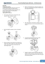
The following instructions are for valves of all sizes.
3.1.
Lubricate the stem thrust seal (7) and the stem seal(9)
with appropriate lubricant.
3.2.
Place the stem thrust seal (7) on the stem (4).
3.3.
Insert the stem (4) horizontally into the center body (1) with the
threaded side first and carefully guide it up through the stem bore.
3.4.
Holding the stem (4) up insert the stem seal (9) over the stem
(4) and into the stem bore. Place the follower (10) and O-ring (10B),
slide bearing (10A), two disc springs (11), and Thread the stem nut
(12) onto the stem (4).
3.5.
Tighten the stem nut onto the stem according to
table 1
.
3.6.
Add the tab lock washer (13).
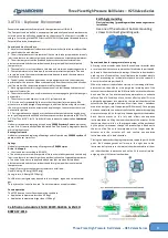
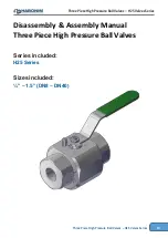
Handles assembly for all valve sizes
3.7.
Lubricate the stem thrust seal (7) and the stem seal(9)
with appropriate lubricant.
3.8.
Place the stem thrust seal (7) on the stem (4).
3.9.
Insert the stem (4) horizontally into the center body (1) with the threaded side first and carefully
guide it up through the stem bore.
3.10.
Holding the stem (4) up insert the stem seal (9) over the stem
(4) and into the stem bore. Place the follower (10) and O-ring (10B), slide
bearing (10A), two-disc springs (11), and Thread the stem nut (12) onto
the stem (4).
3.11.
Tighten the stem nut onto the stem
according to
table 1
3.12.
Add the tab lock washer (13).
3.13.
Place the handle (14) on the top of the tab
lock washer.
3.14.
Place the serrated washer (15) and tighten
the handle nut (16) onto the stem according
to
table 1
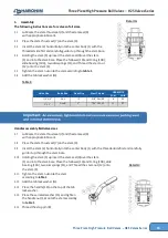
3.15.
Thread the stop pin (8)
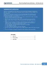
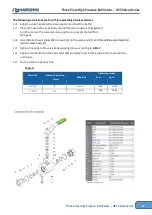
Valve Size
Body Size
Stem Size
Stem Thread
HERMETIX
N-m
Lb-In
1/4”
-
3/4”
Size A
1/2”
3/8”
-24UNF
6
53
1”
-
1.5”
Size B
1”
7/16”
- 20 UNF
11
97
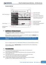
Detail A:
Table 1:
Detail A:
Detail A:


