background image

iii

iii

About This Manual

This manual uses special attention icons to alert the reader of important 

safety concerns, information important to reliable operation of the controls 

or helpful installation/setup information. 

Safety:

 Indicates a condition which may cause severe personal 

injury, death, or major property damage.

Important Information:

 Indicates information which requires 

special attention for correct operation of the control.

Your Benefit: Indicates helpful installation or setup information.

For operating instructions, refer to the 

Operation Manual.


For programming instructions, refer to the  

Programming Guide


Documentation

Summary of Contents for HTE-01

Page 1: ...Installation Pairing Manual Smarter Control Solutions ...

Page 2: ...i This page is intentionally left blank ...

Page 3: ...used with a 24 VAC power source or battery power only DO NOT APPLY supply voltage above 30 VAC DO NOT expose the HTE 01 Thermostat to voltage fluctuations of more than 2 4 VAC 10 of nominal power rating DO NOT install the HTE 01 Thermostat in a bathroom or area of excessive moisture DO NOT expose the HTE 01 Thermostat or HTM 01 Base Module to water DO NOT store the HTE 01 HTM 01 where temperatures...

Page 4: ...ation Safety Indicates a condition which may cause severe personal injury death or major property damage Important Information Indicates information which requires special attention for correct operation of the control Your Benefit Indicates helpful installation or setup information For operating instructions refer to the Operation Manual For programming instructions refer to the Programming Guide...

Page 5: ...w 2 System Dip Switch Configuration 3 HTM 01 Base Module Installation 4 6 LED Status Indication 7 HTE 01 Thermostat Installation 8 Power Installation 9 Boot Screen Display 10 Device Pairing 11 12 Home Screen Controls 13 16 Appendix A Wiring Diagrams 17 21 Appendix B Warranty Information 22 23 Appendix C Specifications 24 Appendix D Compliance 25 26 Designed and Engineered in New York U S registere...

Page 6: ...at all parts are present in the package HTE 01 Thermostat with Mounting Plate 2 AA Alkaline Batteries HTM 01 Base Module Wiring Harness 2 Mounting Screws 2 Wall Anchors HTM 01 Base Module with Double sided Mounting Tape HTM 01 Base Module Water Leak Sensor Cable ...

Page 7: ...pproximately 50 feet through standard building materials PTAC Packaged Terminal AC WSHP Water Source Heat Pump HWSHP Hybrid Water Source Heat Pump FCU Fan Coil Mini Split Unit UNI Unitary AC Furnace The HTE 01 thermostat and HTM 01 base module are paired when supplied as a set from the factory If base modules are added or if pairing is required in the field see pages 11 12 for the device pairing p...

Page 8: ...witches over to Heat OFF O Heating is default switches over to Cool If more than one appliance type dip switch 1 5 is selected error code will be displayed System Dip Switch Configurations 1 PTAC Packaged Terminal Unit Factory Default 2 FCU Fan Coil Unit Mini Split 3 WSHP Water Source Heat Pump 4 HWSHP Hybrid Water Source Heat Pump 5 UNTY Unitary AC Furnace 6 O B Terminal Selection Heat Pump Only ...

Page 9: ... NOT mount the Base Module in locations where temperatures may exceed 104 F 40 C For best results assure that the harness is long enough to reach the intended location before mounting the base module Wire the Base Module Using the Base Module Wiring Harness provided wire the Base Module to the appliance Choose the appropriate wiring diagram from Appendix A based on System Type Heating Cooling Stag...

Page 10: ...the base module and the thermostat The HTM 01 can be mounted on the inside of an enclosure behind louvers or grill Figure 1 For units with a sheet metal cabinet mount the HTM 01 on the outside of the cabinet Figure 2 Figure 1 Units with louvers grill or plastic cover Inside Cabinet Figure 2 Units with sheet metal enclosures Outside Cabinet ...

Page 11: ...HVAC units with an open bottom place as close to the bottom as possible while avoiding places where furnishings or cleaning equipment can cause damage Figure 3 Figure 3 Units with open bottoms Inside Cabinet ...

Page 12: ...tify mode initiated by the thermostat or web application Alternating Green Red Factory Reset Hold the PAIR button for 10 seconds and it begins to flash Release and press again briefly to reset x y Flashing x times Green then y times Red Firmware Version Indicates version x y eg 2 green then 7 green version 2 7 Press and release PAIR button within 10 seconds of power up n Flash Red n times Base Mod...

Page 13: ...loor Select an area with average temperature and good air circulation BE SURE that the UP symbol is correctly oriented DO NOT MOUNT the thermostat near any heat source behind doors or curtains in corners in direct sunlight in areas of high humidity or where water is present AVOID mounting the Thermostat on an exterior wall ...

Page 14: ...erminations provided and tighten the screws Power Installation Hardwired Installation Battery Installation Battery installation is optional if Thermostat is hardwired R and C terminal connected to 24 volt only power Wire Specifications Shielded or non shielded 18 22 gauge thermostat wire Please insert 2 AA Alkaline batteries included High performance lithium batteries may be used and are recommend...

Page 15: ... the following error message is displayed When the HTE 01 Thermostat is first powered all segments are briefly displayed Next the firmware version is displayed for 2 seconds Then the display briefly shows the system type which is dependent on the dip switch settings ...

Page 16: ...the HTE 01 Thermostat and set the 10 minute countdown timer in action This will allow pairing of up to eight base modules Note To exit the Pairing process hold the Mode and Fan button until a beep is played 2 To initiate the Pairing process on each HTM 01 base module press and hold the PAIR button for between 3 10 seconds until the connection status LED flashes green The table on page 7 shows the ...

Page 17: ...ountdown timer As the HTE 01 Thermostat pairs with each HTM 01 Base Module the number of paired modules is displayed A maximum of 8 base modules can be paired with each thermostat If there are eight base modules already paired with the thermostat will be displayed for 3 seconds before returning to the previous screen Note New modules will always be assigned to the lowest available number ...

Page 18: ...13 Home Screen 1 2 3 4 5 6 7 9 10 11 12 13 14 8 ...

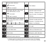
Page 19: ...ndicator status only shown when on battery power used Full Half Low Replace 10 Schedule running indicator Schedule Schedule running1 Blank No Schedule 4 System type 11 Set point 5 Room temperature 12 Celsius or Fahrenheit units 6 Mode status 13 Emergency heat indication 7 Additional system type text 14 Fan speed indication 1 Schedule must be activated for the time schedule status to be displayed S...

Page 20: ...15 HTE 01 Thermostat Controls 1 2 3 4 5 Front View Bottom Side View ...

Page 21: ...e maintained until the Next schedule period Set point is changed to the scheduled value Mode button is held for 3 seconds displaying Schedule Perm Override To change the temperature units between F and C simultaneously press the and buttons briefly Mode Cycle through Operation modes Fan Cycle through desired Fan Speeds Manual Reset Reboots the thermostat system only To save energy the display will...

Page 22: ...peed fan operation In a single speed fan system wires for Gh Gm and Gl should be connected to the fan relay output of the appliance Always refer to the equipment manufacturer s specifications for remote thermostat operation Appendix A Wiring Diagrams ...

Page 23: ... support two speed fan operation In a single speed fan system wires for Gh Gm and Gl should be connected to the fan relay output of the appliance Always refer to the equipment manufacturer s specifications for remote thermostat operation ...

Page 24: ... support two speed fan operation In a single speed fan system wires for Gh Gm and Gl should be connected to the fan relay output of the appliance Always refer to the equipment manufacturer s specifications for remote thermostat operation ...

Page 25: ... support two speed fan operation In a single speed fan system wires for Gh Gm and Gl should be connected to the fan relay output of the appliance Always refer to the equipment manufacturer s specifications for remote thermostat operation ...

Page 26: ... support two speed fan operation In a single speed fan system wires for Gh Gm and Gl should be connected to the fan relay output of the appliance Always refer to the equipment manufacturer s specifications for remote thermostat operation ...

Page 27: ...es consumables such as batteries will be free from defects in material and workmanship under normal use and regular service and maintenance y y For warranty issues please contact the HVAC professional that installed this product y y You can register your products in two ways Email y y Please go to warrantyregistration habitat support Mail y y Please complete the Warranty Registration Form and mail...

Page 28: ...y ______________________________________________________________________ EMAIL ____________________________________________________________________ Thermostat Model ___________________ Serial Number ____________________ Module Model _____________________ Serial Number ______________________ Installed Date _____________________________________ Mail to Habitat Technologies Warranty Registration Dept...

Page 29: ...C 2 AA batteries Operating Ambient 32 F 122 F 0 C 50 C Operating Humidity 95 Non condensing RH Program 5 2 7 days Dimension 3 93 W x 3 93 H x 1 1 D Frequency ISM Band 915MHZ Model HTM 01 Base Module Load Rating 1 amp per terminal 1 5 amp maximum all terminals combined Power Source 18 to 30 VAC NEC Class II 50 60 Hz 44 mA min 24 VAC Add 27 mA per relay 1 2 or 3 plus 44 mA for HTZ 01 Operating Ambie...

Page 30: ...gainst harmful interference in a residential installation This equipment generates uses and can radiate radio frequency energy and if not installed and used in accordance with the instructions may cause harmful interference to radio communications However there is no guarantee that interference will not occur in a particular installation If this equipment does cause harmful interference to radio o...

Page 31: ...stance d au moins 20 cm entre l antenne et toute personne INDUSTRY CANADA This device complies with Industry Canada license exempt RSS standard s Operation is subject to the following two conditions 1 this device may not cause interference and 2 this device must accept any interference including interference that may cause undesired operation of the device Le présent appareil est conforme aux CNR ...

Page 32: ...Designed and Engineered in New York U S Registered Trademark Patents pending www habitattechnologies com HC IM HTE 01 HTM 01 2020 05 v2 Smarter Control Solutions ...

Reviews: