background image

Operating instructions 36009 


Welding device 

PQ-18 


Page 10 of


14 

Edition: 03/0404 

Subject to alterations 

6. Illustrations 


1 2 

11 

10 

12 


Illustration 1:   Overall view of PQ-18 


Welding plate 
Welding tool 
Locking spring 
Securing bracket 
Guiding tongs 
Holding device 

7
8
9

10
11
12

Clamping screw 
Label 
Axle pin 
Guide bar 
Guide head 
Knurled nut 


Ill. 2:   Polycord joint with bead


Ill. 3:   Polycord joint after grinding


Summary of Contents for PQ-18

Page 1: ...elts The joining operation is by blunt welding Ends of the belt are melted by pressing them against the surface of a precisely regulated hot welding plate After sufficient heating belt ends are presse...

Page 2: ...dering of accessories spare parts 5 1 5 Warranty 5 1 6 Technical advice 5 2 Mode of operation 6 3 Initial start up 6 4 Welding of Polycord round belts 7 5 Service 8 5 1 Maintenance 8 5 2 Measuring of...

Page 3: ...n maintenance or repair The indications given herein refer to the use of the machines according to their designated purpose by skilled personnel In case of doubt or if further detailed information is...

Page 4: ...y Qty Item Order No 1 Welding tool 230V EURO 709 008 or 1 Welding tool 120V USA 709 006 1 Guiding tongs with holding device 690 240 1 Operating instruction 1 3 1 Available accessories Also refer to ch...

Page 5: ...numbers and if applicable the required electric voltage for connection to the mains WARNING The use of parts by other manufacturers not meeting Habasit specifications is not admissible Habasit declin...

Page 6: ...evice see illustration 1 Check parallel adjustment of welding plate to flat support area of handle of welding tool 2 When laid down on a table the welding plate may not touch the supporting table Chec...

Page 7: ...s of the guiding tongs 5 by hand so that the guiding tongs 5 can not close any further This makes the belt ends stay in contact with the welding plate but without pressure about 5 10 s depending on th...

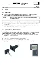
Page 8: ...ically inspect the power supply cable and connector plug for defects insulation damage etc and rectify or replace with the correct type where necessary 5 2 Measuring of the plate temperature Check the...

Page 9: ...the maximum value of 280 C 538 F or below 260 C 502 F the heating control is to be adjusted as follows Move adjustment potentiometer of the heating control using a screwdriver turning it ever so sligh...

Page 10: ...ions 1 2 5 4 11 8 10 6 7 9 12 3 Illustration 1 Overall view of PQ 18 1 2 3 4 5 6 Welding plate Welding tool Locking spring Securing bracket Guiding tongs Holding device 7 8 9 10 11 12 Clamping screw L...

Page 11: ...al data Belt diameter mm in 2 15 0 08 0 6 Temperature unsolicited C F 270 520 Max deviation of plate temperature C F 10 18 Heating up time to 270 C 520 F min 14 Power consumption W 40 200 Voltage V 23...

Page 12: ...03 0404 Subject to alterations 8 Drawing and spare part numbers 700024 702024 709006 120Vac USA plug 709008 230Vac Euro plug 701015 700534 700025 702021 701022 701020 701017 700029 700027 702020 70251...

Page 13: ...ccessories 9 1 Cutting device S 16 The cutting device S 16 operating instruction 3890 is a manual cutting tool to cut Polycord round belts to the required length before the Quickmelt joining procedure...

Page 14: ...of any kind are made as to their accuracy or suitability for particular applications The data provided herein are based on laboratory work with small scale test equipment running at standard conditio...

Reviews: