background image

Operating instructions 3745


Flexproof-Cutter 

AF-603 


Page 14 of


20 

Edition: 01/0512 

Subject to alterations 

8. Drawings 


Summary of Contents for AF-603

Page 1: ...AF 603 The preparing device die cutting machine AF 603 serves for the accurate zigzag shape die cutting of Habasit belts and tapes up to a width of 600 mm and a thickness of 8 mm using the Flexproof system It is suitable for Habasit standard finger geometries with the pitches of 8 10 or 20 mm with different cutting heads Materials over 600 mm wide can be processed also but the recommended maximum ...

Page 2: ...start up 6 4 Die cutting of belt tape ends 7 4 1 Die cutting of belts tapes up to 600 mm 24 in width 7 4 2 Die cutting of belts tapes up over 600 mm 24 in width 8 4 2 1 Die cutting of the already cut to length first belt tape end 8 4 2 2 Die cutting of the already cut to length second belt tape end 9 5 Service 10 5 1 Maintenance 10 5 2 Exchange of the die cutting head 10 5 3 Replacement of cutting...

Page 3: ...evice be carried out by skilled personnel or monitored by responsible specialists For reasons of scope these instructions cannot cover all possible aspects of operation maintenance or repair The indications given herein refer to the use of the tools according to their designated purpose by skilled personnel In case of doubt or if further detailed information is required please contact the manufact...

Page 4: ...for cutting head 10 120 1 4 Ordering of accessories spare parts Spare parts and accessories can be ordered directly from the manufacturer Address Habasit Italiana S p A Via A Meucci 8 Zona Industriale I 31029 Vittorio Veneto TV Tel 39 438 91 13 Fax 39 438 91 2374 Please accurately describe the parts required State the numbers according to Section 8 Drawings WARNING The use of parts by other manufa...

Page 5: ...d for the following die cutting step The exchangeable die cutting head 23 is equipped with two cutting blades 21 which are protected by the holding down bracket 22 when the machine is not in operation During the punching operation the holding down bracket 22 holds the belt tape firmly on the cutting pad 17 As cutting pad 17 a hard plastic plate is used The machine frame has a slit on each side whi...

Page 6: ...ccording to the desired cutting pattern See 5 2 Exchange of the die cutting head Set indexing device 4 to the corresponding cutting head finger pitch 8 mm 0 32 in or 10 mm 0 4 in 20 mm 0 8 in 2 crank rotations on 10 mm 0 4 in setting Loosen knurled screw 3 press index lever 2 against machine frame and slide it to the desired punching pitch setting rotate crank 5 until index lever 2 snaps in then t...

Page 7: ...push button 9 the first cutting operation is effected Press push button 9 only until the cutting blades 21 have completely pierced the product to avoid excessive wear of the cutting pad 17 INDICATION The cutting operation can only be implemented when the index lever 2 is snapped in Shift die cutting head 23 by one finger pitch to the left side by turning crank 5 clockwise to the next snapping in w...

Page 8: ...ight angles to the required length The processing length consists of endless belt tape length 198 mm 7 8 in 4 2 1 Die cutting of the already cut to length first belt tape end Move punching carriage 18 to the starting position on the right side Set the front right hand stop 10 to the 0 point on the mm scale 16 and lock it Set the rear right hand stop 10 to 50 mm on the mm scale 16 and lock it Remov...

Page 9: ...nder 4 1 Lift clamping bars 13 Remove belt tape from die cutting machine With tapes wider than 1100 mm 44 in the preceding cutting process has to be repeated Remove masking tape from cutting pad 17 4 2 2 Die cutting of the already cut to length second belt tape end Move punching carriage 18 to the starting position on the right side Reinstall the front right hand stop 10 and set it a half punching...

Page 10: ...e retainer 24 Slide other die cutting head 23 from the right into the retainer 24 against the stop so that the smaller blade distance faces towards the front Tighten both socket head cap screws M8 20 on the die cutting head retainer 24 Attach protecting hood 11 with both socket head cap screws M5 19 to intermediate plate of punching carriage 18 CAUTION Always close compressed air valve 7 before ex...

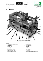
Page 11: ...n 1 Flexproof Cutter AF 603 Legend 1 2 3 4 5 6 7 8 9 Compressed air pressure gauge Index lever Knurled screw Indexing device Crank Hose nozzle Compressed air valve Clamping device switch Push button die cutting 10 11 12 13 14 15 16 17 18 Right hand stop Protecting hood Setscrew Clamping bar Cutting table Left hand stop Scale mm Cutting pad Punching carriage intermediate plate ...

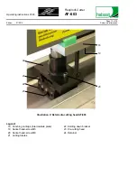
Page 12: ...ion 01 0512 Subject to alterations 24 20 23 22 21 18 19 Illustration 2 Details die cutting head AF 603 Legend 18 19 20 21 Punching carriage intermediate plate Socket head screw M5 Socket head screw M8 Cutting blades 22 23 24 Holding down bracket Die cutting head Retainer ...

Page 13: ... Subject to alterations 7 Technical data Nominal belt tape width mm in 600 24 Max belt tape width recommended mm in 1100 44 Max belt tape thickness mm in 8 0 32 Max compressed air pressure bar psi 6 87 Dimensions L x W x H mm in 940 x 430 x 560 37 x 17 x 22 Net weight kg lbs 85 187 ...

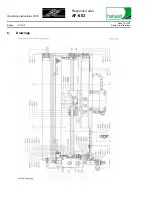
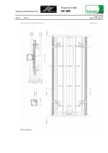
Page 14: ...Operating instructions 3745 Flexproof Cutter AF 603 Page 14 of 20 Edition 01 0512 Subject to alterations 8 Drawings ...

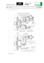
Page 15: ...Operating instructions 3745 Flexproof Cutter AF 603 Page 15 of 20 Edition 01 0512 Subject to alterations ...

Page 16: ...Operating instructions 3745 Flexproof Cutter AF 603 Page 16 of 20 Edition 01 0512 Subject to alterations ...

Page 17: ...Operating instructions 3745 Flexproof Cutter AF 603 Page 17 of 20 Edition 01 0512 Subject to alterations ...

Page 18: ...eaning 1 1 Clean the Flexproof cutter after use remove residual matter A 1 2 Compressed air filter drain condensate clean filter If necessary replace A 2 Lubrication 2 1 Lubricate threaded spindle with ball bearing grease B 2 2 Lubricate indexing gears with ball bearing grease B 3 Wear parts 3 1 Check the cutting pad 17 for wear If necessary turn on other side or replace it A 3 2 Check cutting bla...

Page 19: ...of first placing in operation Actions to be performed see checklist Next Performed Next Performed Next Performed Next Performed daily work not recorded Check Initials Date Check Initials Date Check Initials Date Check Initials Date 1 2 Compressed air filter 2 1 Threaded spindle 2 2 Indexing gears 3 1 Cutting pad 3 2 Cutting blades 4 1 Pneumatic system Observations repairs ...

Page 20: ...es of any kind are made as to their accuracy or suitability for particular applications The data provided herein are based on laboratory work with small scale test equipment running at standard conditions and do not necessarily match product performance in industrial use New knowledge and experiences can lead to modifications and changes within a short time without prior notice BECAUSE CONDITIONS ...

Reviews: