


Figure 9:
Installing the oil tank
(see Chapter 12.2.).
2. Position the tank so that the filler neck with filter is
located on the outside.
3. Mount tank screen panel to the rear wall (see figures
1, 2, 6(B) and 10), by hooking the panel with the 2
hooks into the holes next to the flue pipe spigot.
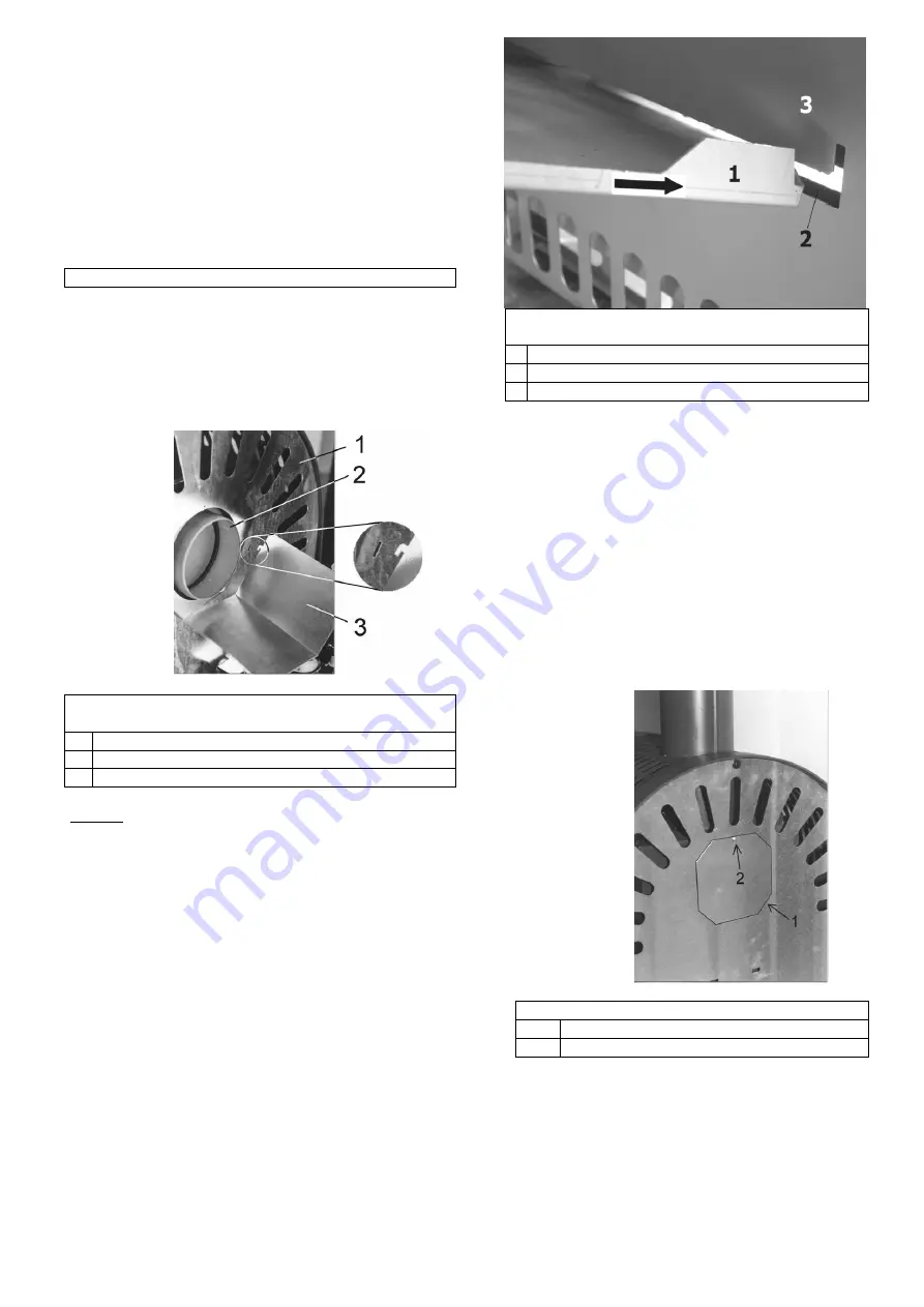
Figure 10:
Viking 468.50, Installing the tank screen
panel
1
Rear wall
2
Flue pipe spigot
3
Tank screen panel
Oil pan:
In the event that oil-carrying stove components should
start to leak, each oil stove is equipped with an oil pan
(see Figures 1 + 2). The oil stove “Viking 468.50” is
furnished with a second oil pan (see Figure 1) if this
appliance is equipped with a tank. The oil pan opening
always faces up so that dripping oil can be collected.
With the “Ibiza” model it is necessary to install the oil
guide plate enclosed in the tank set. To do so, remove
the prepared opening in the rear wall by breaking out
the sheet metal and insert the oil guide plate (see
Figure 2, 6(A)). For emptying or cleaning the oil pan
can be removed either from the front or from the rear.
Figure 11:
Ibiza 469.50, Installation of oil guide
plate
1 Oil guide plate
2 Recess
3 Rear wall
8.
Conversion instructions for the model “Viking
468.50” to vertical flue pipe connection
On the model “Viking 468.50” it is possible to convert
from horizontal to vertical flue pipe connection:
1. Break out the opening in the round bend at the top.
2. Unscrew pipe spigot rear and pipe spigot lid at the
top (see Figure 2, exchange and re-install in the
new position.
3. It is imperative to cover the hole of the pipe spigot
lid in the appliance rear wall to avoid impairment o
the installation wall through heat radiation (e.g.
wallpaper)! To do so, install the enclosed cover
disc (1) to the rear wall using the sheet metal
screw (2) (see Figure 12).
Figure 12:
Oil stove Viking 468.50
1
Cover disc
2
Sheet metal screw


