background image


21 

Connecting the Ethernet cables 

Connecting a copper Ethernet port 

1.


Connect one end of the Ethernet cable to the copper Ethernet port of the device, and the other end 

to the Ethernet port of the peer device.  

2.


After powering on the device, examine the LEDs of the fixed copper Ethernet port. 
For more information about the LED description, see "

Appendix B LEDs

." 

Connecting a fiber port 

No transceiver module is provided with the device. The device supports only LC-type fiber connectors. For 

transceiver module specifications, see "

Appendix A Chassis views and technical specifications

." 

Follow these guidelines when you connect an optical fiber: 


Never stare into an open fiber port, because invisible rays might be emitted from the fiber port. 


Cover the dust plug if no optical fiber connector is connected to the fiber port.  


Never bend or curve a fiber when connecting it. After a fiber is installed correctly, the bend radius 

must be not less than 10 cm (3.94 in). 


Keep the fiber end clean. 


Make sure the Tx and Rx ports on a transceiver module are correctly connected. 

To connect the device to the network through an optical fiber: 

1.


Remove the dust plug on the fiber port. 

2.


Remove the dust cover from the transceiver module, and insert the transceiver module into the fiber 
port. 

3.


Remove the dust cover of the optical fiber connector. 

4.


Identify the Rx and Tx ports on the transceiver module. Plug the LC connectors at one end of the 
optical fiber into the Rx and Tx ports of the transceiver module and the other end into the Tx and 

Rx ports of the peer device.  

Summary of Contents for WX5540H

Page 1: ...H3C WX5540H Access Controller Installation Guide New H3C Technologies Co Ltd http www h3c com hk Document version 6W102 20170421...

Page 2: ...her trademarks that may be mentioned in this manual are the property of their respective owners Notice The information in this document is subject to change without notice Every effort has been made i...

Page 3: ...ext represents commands and keywords that you enter literally as shown Italic Italic text represents arguments that you replace with actual values Square brackets enclose syntax choices keywords or ar...

Page 4: ...ORTANT An alert that calls attention to essential information NOTE An alert that contains additional or supplementary information TIP An alert that provides helpful information Network topology icons...

Page 5: ...screenshots and other information in the examples differ from what you have on your device Obtaining documentation To access the most up to date H3C product documentation go to the H3C website at htt...

Page 6: ...he device by using front mounting brackets and a rack shelf 12 Installing the device by using front mounting brackets and slide rails 13 Grounding the device 15 Installing a lightning protector for a...

Page 7: ...memory usage of the device 32 Displaying the operational status of the built in fans 33 Displaying the operating state of a power module 34 Rebooting the device 34 Restrictions and guidelines 34 Conf...

Page 8: ...chassis and installation tools away from walk areas Keep the chassis clean and dust free Do not place the device near water or in a damp environment Prevent water or moisture from entering the device...

Page 9: ...ing high relative humidity can cause poor insulation electricity creepage mechanical property change of materials and metal corrosion Lasting low relative humidity can cause washer contraction and ESD...

Page 10: ...Cl2 0 01 NO2 0 04 Cooling The device uses left to right airflow for heat dissipation Plan the installation site for adequate ventilation H3C recommends that you leave a minimum of 10 cm 3 94 in of cl...

Page 11: ...he alligator clip to the rack 5 Make sure the rack is reliably grounded Figure 2 Attaching an ESD wrist strap 1 ESD wrist strap 2 Lock 3 Alligator clip EMI All electromagnetic interference EMI sources...

Page 12: ...supply Accessories Grounding cable provided M4 screw provided Front mounting bracket provided Rear mounting bracket provided Rubber feet provided Console cable provided M6 cage nut user supplied M6 s...

Page 13: ...current Use electromagnetic shielding when necessary Lightning protection The grounding cable of the chassis is reliably grounded The grounding terminal of the AC power receptacle is reliably grounde...

Page 14: ...you want to open the chassis contact H3C Support for permission Otherwise H3C will not be liable for any consequence caused thereby Confirming installation preparations Before you install the device v...

Page 15: ...inch rack is not available you can place a device on a clean flat workbench as follows 1 Clean the recessed areas on the chassis bottom 2 Attach the four rubber feet to the recessed areas on the chas...

Page 16: ...rack by using the following methods Installing the device by using front and rear mounting brackets Installing the device by using front mounting brackets and a rack shelf Installing the device by us...

Page 17: ...sts Install cage nuts Figure 7 Installing cage nuts 3 Use the screws supplied with the front mounting brackets to secure the front mounting brackets to both sides of the device Figure 8 Attaching the...

Page 18: ...0 Installing rear mounting brackets 6 Supporting the bottom of the device with one hand and holding the front of the device with the other place the device slowly in the rack Attach the front mounting...

Page 19: ...in this example is for illustration only To install the device by using front mounting brackets and a rack shelf 1 Wear the ESD wrist strap and verify that the rack is sturdy and is reliably grounded...

Page 20: ...the device to the front rack posts by using screws and cage nuts as shown in Figure 13 Figure 13 Installing the device in the rack Installing the device by using front mounting brackets and slide rai...

Page 21: ...ts to attach the front mounting brackets to the device as shown in Figure 8 3 Attach the slide rails to the rack See Figure 14 for reference Figure 14 Installing slide rails 4 Holding both sides of th...

Page 22: ...wdriver to remove the grounding screw from the chassis 2 Use the grounding screw to attach one end with ring terminal of the grounding cable to the chassis 3 Connect the other end of the grounding cab...

Page 23: ...16 Figure 17 Grounding the device with the rack 1...

Page 24: ...ble at the installation site hammer a 0 5 m 1 64 ft or longer angle iron or steel tube into the earth to serve as a grounding conductor Weld the yellow green grounding cable to the angel iron or steel...

Page 25: ...double faced adhesive tape to stick the lightning protector onto the device chassis and make sure it is as close to the grounding screw of the device as possible 2 Measure the distance between the pr...

Page 26: ...stall a lightning protector for each network port Connecting the AC power supply to a power strip with lightning protection CAUTION Make sure the PE terminal of the power socket has been securely grou...

Page 27: ...cally opens the electric circuit when the current exceeds the threshold and closes the electric circuit when the current drops below the threshold 6 Multifunctional socket It is used to connect the po...

Page 28: ...because invisible rays might be emitted from the fiber port Cover the dust plug if no optical fiber connector is connected to the fiber port Never bend or curve a fiber when connecting it After a fib...

Page 29: ...not install an AC power module and a DC power module on the same device 1 Remove the filler panel if any from the slot where you want to install a power module with a Phillips screwdriver Keep the re...

Page 30: ...ring on the device connect the grounding cable of the device To connect the AC power cord 1 Pivot the bail latch upward 2 Connect one end of the AC power cord to the AC input power receptacle on the d...

Page 31: ...driver to remove the protection cover from the DC power module 2 Correctly insert the DC plug into the DC power receptacle 3 Use a flat blade screwdriver to fasten the screws on the DC plug 4 Connect...

Page 32: ...l T to start heavy memory test Booting Normal Extended BootWare The Extended BootWare is self decompressing Done H3C WX5540H BootWare Version 5 10 Copyright c 2004 2017 New H3C Technologies Co Ltd Com...

Page 33: ...est for AES passed Known answer test for RSA signature verification passed Known answer test for RSA encrypt decrypt passed Known answer test for DSA signature verification passed Known answer test fo...

Page 34: ...C Support No display or garbled display on the configuration terminal Symptom The configuration terminal does not have display or have a garbled display when the device is powered on Solution To resol...

Page 35: ...iew the software loading process displayed on the HyperTerminal to check for errors If an error exists correct the error For example check for the following errors that might occur When you use XMODEM...

Page 36: ...of the device H3C display version H3C Comware Software Version 7 1 064 ESS 5207 Copyright c 2004 2017 New H3C Technologies Co Ltd All rights reserved H3C WX5540H uptime is 0 weeks 1 day 2 hours 36 min...

Page 37: ...Y N y Please input the file name tar gz cfa0 diag_H3C_20170421 141807 tar gz Diagnostic information is outputting to cfa0 diag_H3C_20170421 141807 tar gz Please wait Save successfully To view the fil...

Page 38: ...ing detailed information about the device Use the display device command to display detailed information about the device H3C display device Slot No Subslot No Board Type Status Max Ports 1 0 WX5540H...

Page 39: ...conds 1 in last 1 minute 1 in last 5 minutes Table 7 Command output Field Description Slot 1 CPU 0 CPU usage Usage of CPU 0 on IRF member device 1 1 in last 5 seconds Average CPU usage in the last 5 s...

Page 40: ...e memory ratio Buffers Cache Buffers Cache used Mem Used Mem Buffers Mem Cached which indicates the physical memory used by applications Buffers Cache free Mem Free Mem Buffers Mem Cached which indica...

Page 41: ...d Power off and power on the device This method cuts off the power of the device forcibly which might cause data loss It is the least preferrred method Restrictions and guidelines Before you reboot th...

Page 42: ...edule a reboot Schedule a reboot to occur at a specific time or date schedule reboot at time date Schedule a reboot to occur after a delay schedule reboot delay time Use either command By default no r...

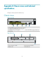
Page 43: ...igure 27 Front view 1 100 1000BASE T autosensing Ethernet ports 1 through 12 2 100BASE FX 1000BASE X SFP ports 13 through 24 3 10GBASE R SFP ports 25 through 28 4 100 1000 BASE T management Ethernet p...

Page 44: ...4 Power receptacle DC power module Figure 30 DC power module 1 Captive screw 2 Power switch 3 Air outlet vent 4 Power receptacle Transceiver module fiber connector and optical fiber views To connect...

Page 45: ...an LC connector 1 LC connector 2 Optical fiber Technical specifications Table 11 Technical specifications Item Specification Console port One 9600 bps default to 115200 bps Gigabit Ethernet port 12 10...

Page 46: ...s Item Specification Model PSR300 12A1 PSR300 12A2 Rate input voltage range 100 VAC to 240 VAC 50 Hz or 60 Hz Rated power 300 W Table 13 DC power module specifications Item Specification Model PSR300...

Page 47: ...ration 7 dBm Table 16 SFP FE LH40 SM1310 specifications Item Specification Central wavelength 1310 nm Transmission distance 40 km 24 86 miles Transmission rate 125 Mbps Connector type Duplex LC Fiber...

Page 48: ...ration 3 dBm Table 19 SFP GE LH40 SM1310 specifications Item Specification Central wavelength 1310 nm Transmission distance 40 km 24 86 miles Transmission rate 1250 Mbps Connector type Duplex LC Fiber...

Page 49: ...dBm Table 22 SFP XG SX MM850 A specifications Item Specification Central wavelength 850 nm Transmission distance 300 m 984 25 ft Transmission rate 10 3125 Gbps Connector type Duplex LC Fiber mode MMF...

Page 50: ...h 1550 nm Transmission distance 40 km 24 86 miles Transmission rate 10 3125 Gbps Connector type Duplex LC Fiber mode SMF Fiber diameter 9 m Transmit power 4 7 to 4 dBm Receive sensitivity 15 8 dBm Sat...

Page 51: ...n LED Mark Status Description Power module 1 status LED PWR1 Steady green Power module 1 is operating correctly Steady yellow Power module 1 is faulty Off No power module is present Power module 2 sta...

Page 52: ...yellow The port is receiving or transmitting data at 100 Mbps Steady green A 1000 Mbps link is present on the port Flashing green The port is receiving or transmitting data at 1000 Mbps Off No link is...

Page 53: ...K Off No power is output or the power module has an output problem Steady green The power is output correctly Figure 36 DC power module LEDs 1 DC power input status LED 2 DC power output status LED Ta...

Page 54: ...usage of the device 32 Displaying the operating state of a power module 34 Displaying the operational status of the built in fans 33 E Electrical safety 1 EMI 4 ESD prevention 3 G General safety recom...

Reviews: