14
CAUTION:
•
Place the PoE injector stable indoors in a well ventilated location.
•
If multiple PoE injectors are installed in one equipment room or maintenance hole, use one
power strip for all these injectors and lead in the power strip from the air switch of the AC power
distribution box.
The PoE1 port on the dual-port H3C PoE injector must be connected to the uplink network through
the LAN1 port, and PoE2 through LAN2. The following procedures use the PoE1 port as an example
to connect the AP.
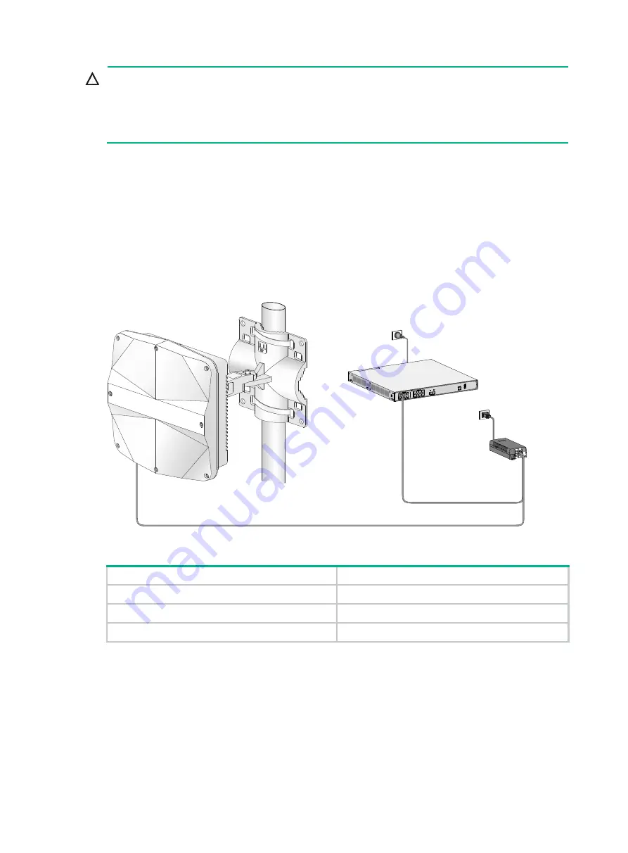
Connecting the AP to a PoE injector and to the network through the Ethernet copper port
1.
Connect the power cord of the injector to an AC power source.
2.
Connect the PoE1 port on the injector to the GE1 port on the AP.
3.
Connect the LAN1 port on the injector to a switch or access controller.
Figure 18 Connecting the AP to a PoE injector and to the network through the Ethernet
copper port
Table 2 Dual-port H3C PoE injector description
Item Specifications
Model ADP060-55V-PoE-GL
Input
100 V – 240 V @ 1.5 A
Output
55 V @ 1100 mA
Connecting the AP to a PoE injector and to the network through the fiber port
1.
Connect the SFP port on the AP to an Ethernet switch or access controller.
LAN1
PoE1
GE1