background image


18 

1. 

Wear an ESD wrist strap and make sure the strap makes good skin contact and is reliably 
grounded. 

2. 

Power off the device. 

3. 

Remove the access panel. For more information, see "

Installing a storage controller

." 

4. 

Install a DIMM: 

a. 

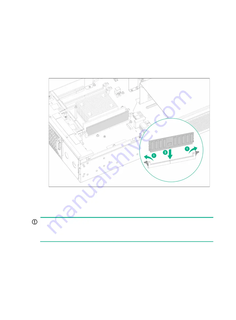
Identify the location of the DIMM slot and open the DIMM slot latches. 

b. 

Align the notch on the DIMM with the connector key in the DIMM slot and press the DIMM 
into the socket until the latches lock the DIMM in place. 

Figure7-13 Installing a DIMM 


5. 

Install the access panel. For more information, see "

Installing a storage controller

." 

Installing an M.2 SSD drive 


IMPORTANT: 

  For system identification, use M.2 SSD drives recommended by H3C. 

  The M.2 SSD drive screw is shipped with the document bag for the chassis. Before installing an 

M.2 SSD drive, keep the screw secure. 


The device supports M.2 SSD drives with dimensions of 22 × 80 mm (0.87 × 3.15 in) and M.2 SSD 
drives with dimensions of 22 × 60 mm (0.87 × 2.36 in). To install an M.2 SSD drive with dimensions 
of 22  ×  60  mm (0.87  ×  2.36  in), adjust the stud location in the  system board. The following 
procedure installs an M.2 SSD drive with dimensions of 22 × 80 mm (0.87 × 3.15 in). 

To install an M.2 SSD drive: 

1. 

Wear an ESD wrist strap and make sure the strap makes good skin contact and is reliably 
grounded. 

2. 

Power off the device. 

3. 

Remove the access panel. For more information, see "

Installing a storage controller

." 

Summary of Contents for SR6602-I AI Series

Page 1: ...H3C SR6602 I IE AI Powered ICT Converged Gateways Installation Quick Start New H3C Technologies Co Ltd http www h3c com Document version 5W102 20210811 ...

Page 2: ...r respective owners Notice The information in this document is subject to change without notice All contents in this document including statements information and recommendations are believed to be accurate but they are presented without warranty of any kind express or implied H3C shall not be liable for technical or editorial errors or omissions contained herein Environmental protection This prod...

Page 3: ... 7 Grounding the device mounted on a workbench 8 Grounding the device mounted in a rack 8 7 Installing internal removable components 9 Installing a storage controller 10 Installing a GPU 16 Installing a DIMM 17 Installing an M 2 SSD drive 18 8 Installing external removable components 19 Installing MIC X interface cards 20 Installing a FIP module 21 Installing SATA drives 22 Installing power suppli...

Page 4: ...repare Phillips screwdrivers with a tip width of 2 5 mm 0 10 in and 6 mm 0 24 in Figure1 1 Tool list 2 Installation accessories CAUTION Wear an ESD wrist strap when installing the device Make sure the wrist strap makes good skin contact and is reliably grounded Figure2 1 Installation accessories 3 Airflow of the device To ensure good ventilation keep the air inlet and outlet vents of the device fr...

Page 5: ...lide rails The device provides multiple chassis rail installation positions on its side panels Attach the chassis rails to the correct positions based on the rack depth For security purposes make sure the front end of each slide rail slides a minimum length of 68 mm 2 68 in into the chassis rail To rack mount the device by using the mounting brackets and slide rails 1 Wear an ESD wrist strap and m...

Page 6: ...Attaching cage nuts to the rack 3 Use a slide rail to mark the cage nut installation positions on the rear rack posts Install cage nuts at the marked positions and attach slide rails to the rack Figure4 2 Attaching slide rails to the rack 4 Use M4 mounting bracket screws to attach the chassis rails and mounting brackets to both sides of the device ...

Page 7: ...ottom of the device aligns the chassis rails with the slide rails and slides the slide rails into the chassis rails until the mounting brackets are flush against the front rack posts 6 Use the M6 rack screws to secure the mounting brackets to the front rack posts Figure4 4 Securing the device to the rack ...

Page 8: ...unting the device To rack mount the device by using the mounting brackets and a rack shelf 1 Wear an ESD wrist strap and make sure the strap makes good skin contact and is reliably grounded 2 Identify the device installation position and secure the rack shelf to the rack 3 Use the mounting brackets to mark the cage nut installation positions on the front rack posts according to the rack shelf posi...

Page 9: ...he mounting brackets to the device 6 Place the device horizontally on the rack shelf Move the device along the rack shelf until the mounting brackets of the device are flush against the front the rack posts 7 Use the M6 rack screws to secure the mounting brackets to the front rack posts Figure4 8 Securing the device to the rack ...

Page 10: ...vice upside down on the workbench and clean the four round holes in the chassis bottom with a dry cloth 2 Attach the four rubber feet to the round holes in the chassis bottom 3 Place the device with upside up on the workbench Figure5 2 Installing the device on a workbench 6 Grounding the device CAUTION Correctly connecting the grounding cable is crucial to lightning protection and EMI protection ...

Page 11: ...the grounding cable Attach the hook to the grounding post and secure the hook with the nut Figure6 1 Grounding the device mounted on a workbench Grounding the device mounted in a rack If the device is installed in a rack you can connect the grounding cable of the device to a grounding terminal on the rack To ground the device by using a grounding terminal on the rack 1 Make sure the rack is reliab...

Page 12: ...ain them first power off the device The internal removable components supported by the device include riser modules GPUs storage controllers DIMMs and M 2 SSD drives These internal removable components are not provided with the device Purchase them yourself as required One GPU support bracket and four screws are shipped with a riser module Three screws are used to attach the GPU support bracket to...

Page 13: ...vice 3 Install the storage controller in the riser module a Align the golden plating of the storage controller with the PCIe slot in the riser module and insert the storage controller into the PCIe slot b Use a Phillips screwdriver to fasten the screw provided with the riser module to secure the storage controller to the riser module Figure7 1 Installing the storage controller in the riser module ...

Page 14: ...ont panel of the device and use a Phillips screwdriver to unlock the screw on the locking lever b Press the blue unlock button on the locking lever to release the locking lever and pull the lever upward The access panel will slide back slightly c Use both hands to hold and lift the access panel Figure7 3 Removing the access panel ...

Page 15: ...ve the screws from the riser module blank and lift the riser module blank from the device Figure7 4 Removing the riser module blank 7 Remove the cable from the drive backplane The cable is used by the system to identify the external SATA drives Keep the removed cable secure ...

Page 16: ... 8 Connect the other end of the storage controller cable to the drive backplane and use a cable clamp to secure the storage controller cable to the side panel of the storage controller Figure7 6 Connecting the storage controller cable to the drive backplane ...

Page 17: ...screw hole on the system board b Align the golden plating of the riser module with the PCIe riser connector on the main board and insert the riser module vertically onto the system board c Fasten the captive screws to secure the riser module to the system board Figure7 7 Installing the riser module in the device 10 Fasten the screws with a Phillips screwdriver to secure the riser module to the cha...

Page 18: ...the access panel on top of the device chassis and align the pegs inside the access panel with the slots on the device side panels b Press the locking lever downwards until it is locked in place c Fasten the screw on the locking lever with a Phillips screwdriver to lock the locking lever Figure7 9 Installing the access panel ...

Page 19: ...skin contact and is reliably grounded 2 Power off the device 3 Attach the GPU support bracket to the GPU Align the three screw holes in the GPU support bracket with the installation holes in the GPU and then use screws to attach the GPU support bracket to the GPU Figure7 10 Attaching the GPU support bracket to the GPU 4 Remove the module blank from the riser module Use a Phillips screwdriver to lo...

Page 20: ...r more information see Installing a storage controller 7 Remove the riser module blank For more information see Installing a storage controller 8 Install the riser module installed with the GPU in the device With a GPU or storage controller installed the riser module installation procedure is the same For more information see Installing a storage controller 9 Use screws to secure the riser module ...

Page 21: ...ive IMPORTANT For system identification use M 2 SSD drives recommended by H3C The M 2 SSD drive screw is shipped with the document bag for the chassis Before installing an M 2 SSD drive keep the screw secure The device supports M 2 SSD drives with dimensions of 22 80 mm 0 87 3 15 in and M 2 SSD drives with dimensions of 22 60 mm 0 87 2 36 in To install an M 2 SSD drive with dimensions of 22 60 mm ...

Page 22: ...Figure7 14 Installing an M 2 SSD drive 7 Install the access panel For more information see Installing a storage controller 8 Installing external removable components CAUTION Install a module or filler panel in each slot Make sure no slot is empty during the device operation Do not hold the handle of a power supply or of a module to move the device Doing so might cause device damage No FIP modules ...

Page 23: ...ce card and then insert it into slot 2 slowly To install an MIC X interface card 1 Wear an ESD wrist strap and make sure the strap makes good skin contact and is reliably grounded 2 Locate the target slot on the FIP module 3 Use a Phillips screwdriver to loosen the captive screws on the filler panel Insert a flat head screwdriver into the hole on the filler panel to pull the filler panel out the s...

Page 24: ... it on a FIP module and then install the FIP module with it on the device To install a FIP module 1 Optional Install MIC X interface cards on the FIP module For the MIC X interface card installation procedure see Installing MIC X interface cards 2 Wear an ESD wrist strap and make sure the strap makes good skin contact and is reliably grounded 3 Face the front panel of the device use a Phillips scr...

Page 25: ... 7 Close the ejector lever until the FIP module is securely seated in the slot Figure8 5 Installing a FIP module Installing SATA drives CAUTION The SATA drives are hot swappable You can install a SATA drive or remove a SATA drive in RAID configuration as indicated by the LED without power off the device To remove a SATA drive not in RAD configuration you must first power off the device For system ...

Page 26: ...s are hot swappable Do not install AC and DC power supplies on the same device The installation procedure is similar for AC and DC power supplies This following figure installs an AC power supply To install a power supply 1 Wear an ESD wrist strap and make sure the strap makes good skin contact and is reliably grounded 2 Remove the filler panel from the target power supply slot if any To install t...

Page 27: ...r supply 9 Connecting power cords CAUTION Before connecting a power cord make sure the device is reliably grounded Make sure each power cord has a separate circuit breaker Before connecting a power cord turn off the circuit breaker for it Use the power cord provided with a power supply to connect power for it Connecting an AC power cord 1 Wear an ESD wrist strap Make sure the wrist strap makes goo...

Page 28: ...ion structure If you orient the DC power cord connector upside down you cannot insert it into the receptacle 4 Use a flat head screwdriver to fasten the screws on the power cord connector to secure the connector to the power receptacle 5 Connect the other end of the DC power cord to the wiring terminals of a DC power source with the negative wire to the negative terminal and the positive wire to t...

Page 29: ...receptacle on the power supply 4 Close the cable clamp and slide it forward until it is flush against the edge of the female connector 5 Connect the other end of the power cord to an AC or high voltage DC power source Figure9 3 Connecting a high voltage DC power cord ...

Reviews: