background image


9-4 

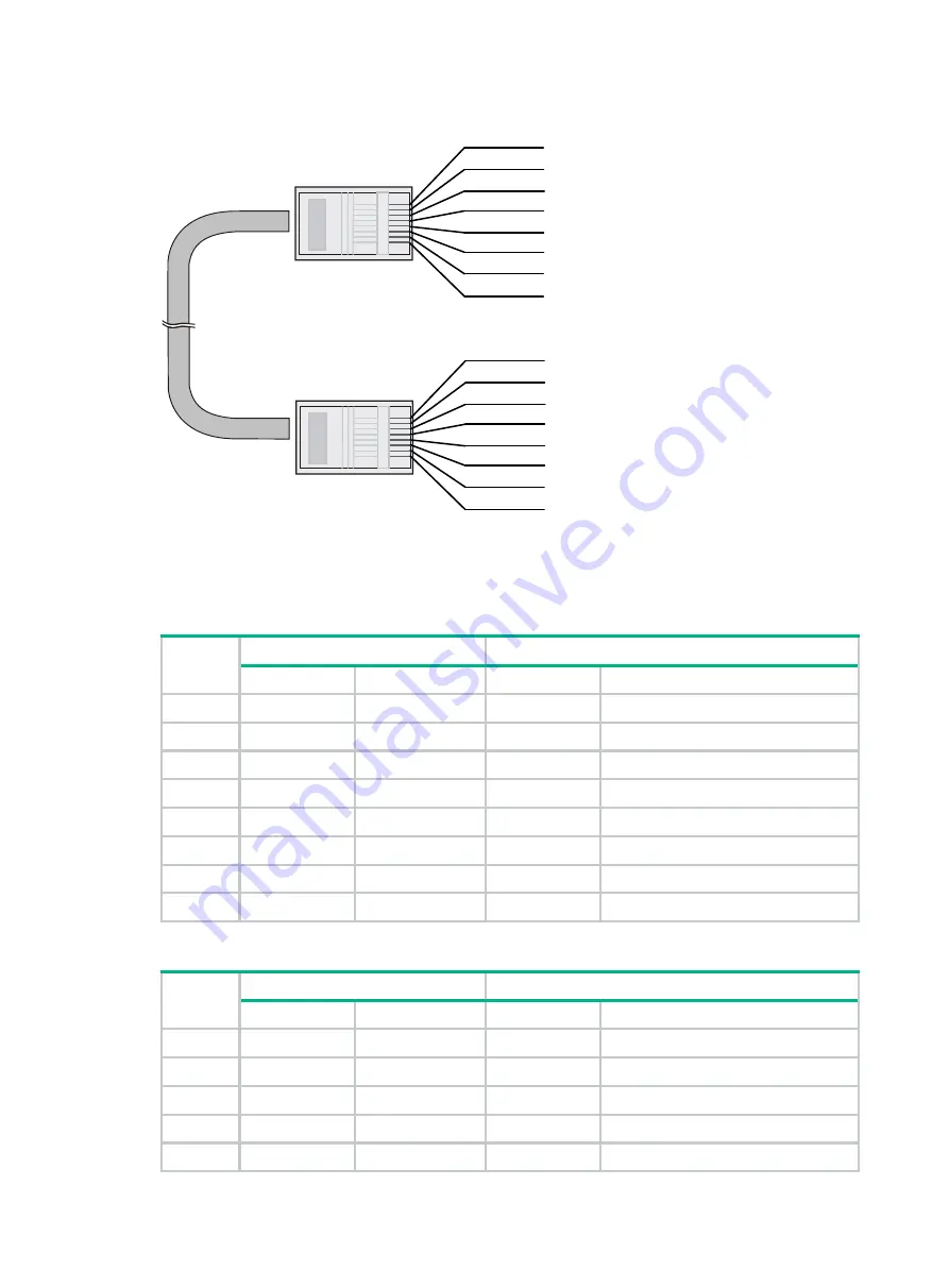
Figure9-5 Crossover cable 


Select an Ethernet twisted pair cable according to the RJ-45 Ethernet port type on your device. An 
RJ-45 Ethernet port can be MDI (for routers and PCs) or MDIX (for switches). 

Table9-4

 an

Table9-5


show their pinouts.  

Table9-4 RJ-45 MDI port pinouts 

Pin 

10BASE-T/100BASE-TX 

1000BASE-T 

Signal 

Function 

Signal 

Function 

Tx+ 

Sends data 

BIDA+ 

Bi-directional data cable A+ 

Tx- 

Sends data 

BIDA- 

Bi-directional data cable A- 

Rx+ 

Receives data 

BIDB+ 

Bi-directional data cable B+ 

Reserved 

N/A 

BIDC+ 

Bi-directional data cable C+ 

Reserved 

N/A 

BIDC- 

Bi-directional data cable C- 

Rx- 

Receives data 

BIDB- 

Bi-directional data cable B- 

Reserved 

N/A 

BIDD+ 

Bi-directional data cable D+ 

Reserved 

N/A 

BIDD- 

Bi-directional data cable D- 


Table9-5 RJ-45 MDIX port pinouts 

Pin 

10BASE-T/100BASE-TX 

1000BASE-T 

Signal 

Function 

Signal 

Function 

Rx+ 

Receives data 

BIDB+ 

Bi-directional data cable B+ 

Rx- 

Receives data 

BIDB- 

Bi-directional data cable B- 

Tx+ 

Sends data 

BIDA+ 

Bi-directional data cable A+ 

Reserved 

N/A 

BIDD+ 

Bi-directional data cable D+ 

Reserved 

N/A 

BIDD- 

Bi-directional data cable D- 

Crossover cable

white/orange

orange

white/green

green

white/orange

orange

white/green

blue

white/blue

green

white/brown

brown

1

2

3

4

5

6

7

8

blue

white/blue

white/brown

brown

1

2

3

4

5

6

7

8

Summary of Contents for SecPath F1000-AI-X0

Page 1: ...H3C SecPath F1000 AI X0 Firewalls Installation Guide New H3C Technologies Co Ltd http www h3c com Document version 6W100 20210205 ...

Page 2: ...respective owners Notice The information in this document is subject to change without notice All contents in this document including statements information and recommendations are believed to be accurate but they are presented without warranty of any kind express or implied H3C shall not be liable for technical or editorial errors or omissions contained herein Environmental protection This produc...

Page 3: ...eplace with actual values Square brackets enclose syntax choices keywords or arguments that are optional x y Braces enclose a set of required syntax choices separated by vertical bars from which you select one x y Square brackets enclose a set of optional syntax choices separated by vertical bars from which you select one or none x y Asterisk marked braces enclose a set of required syntax choices ...

Page 4: ...twork device such as a router switch or firewall Represents a routing capable device such as a router or Layer 3 switch Represents a generic switch such as a Layer 2 or Layer 3 switch or a router that supports Layer 2 forwarding and other Layer 2 features Represents an access controller a unified wired WLAN module or the access controller engine on a unified wired WLAN switch Represents an access ...

Page 5: ...hardware model configuration or software version It is normal that the port numbers sample output screenshots and other information in the examples differ from what you have on your device Documentation feedback You can e mail your comments about product documentation to info h3c com We appreciate your comments ...

Page 6: ...F1000 AI 50 firewall 16 Installing a power supply for an F1000 AI 60 F1000 AI 70 F1000 AI 80 or F1000 AI 90 firewall 17 Installing an interface module 18 Installing a drive 19 Installing a drive for an F1000 AI 10 firewall 19 Installing a drive for other firewalls than the F1000 AI 10 19 Connecting Ethernet cables 20 Connecting a copper Ethernet port 20 Connecting a fiber port 20 Connecting power ...

Page 7: ...al statistics of the firewall 5 38 Displaying transceiver module information 5 38 Rebooting the firewall 5 39 6 Troubleshooting 6 41 Power supply failure 6 41 Configuration terminal display issue 6 41 Password loss 6 41 Cooling system failure 6 42 Software loading failure 6 42 7 Appendix A Chassis views and technical specifications 1 Chassis views 1 F1000 AI 10 1 F1000 AI 20 F1000 AI 30 F1000 AI 5...

Page 8: ... LEDs 1 9 Appendix C Cables 9 1 Console cable 9 1 RJ 45 to DB9 console cable 9 1 Micro USB console cable 9 1 Ethernet twisted pair cable 9 2 Introduction 9 2 Making an Ethernet twisted pair cable 9 5 Optical fiber 9 5 ...

Page 9: ... attention to important information that if not understood or followed can result in data loss data corruption or damage to hardware or software General safety recommendations Do not place the firewall on an unstable case or desk The firewall might be severely damaged in case of a fall Make sure the ground is dry and flat and anti slip measures are in place Keep the chassis and installation tools ...

Page 10: ...t emit invisible laser light Do not stare into beams or view directly with optical instruments when the firewall is operating The firewall is a Class 1 laser device Before you disconnect the fiber connector execute the shutdown command in interface view to disable the optical source Install dust caps to disconnected optical fiber connectors and ports on disconnected transceiver modules to avoid da...

Page 11: ...humidity in the equipment room Lasting high relative humidity can cause poor insulation electricity leakage mechanical property change of materials and metal corrosion Lasting low relative humidity can cause washer contraction and ESD and bring problems including loose captive screws and circuit failure High temperature can accelerate the aging of insulation materials and significantly lower the r...

Page 12: ...ts airflow direction meeting the ventilation requirements Reserve a minimum clearance of 100 mm 3 94 in around the inlet and outlet air vents Make sure the installation site has a good cooling system The F1000 AI 10 firewall provides front side intake and rear side exhaust airflow for heat dissipation The F1000 AI 20 F1000 AI 30 F1000 AI 50 F1000 AI 60 F1000 AI 70 F1000 AI 80 and F1000 AI 90 firew...

Page 13: ... ESD wrist strap is provided with the firewall Purchase one yourself Before you attach an ESD wrist strap make sure the rack or the workbench is reliably grounded To attach the ESD wrist strap 1 Wear the wrist strap on your wrist 2 Lock the wrist strap tight around your wrist to keep good contact with the skin 3 Secure the wrist strap lock and the alligator clip lock together 4 Attach the alligato...

Page 14: ...llow these guidelines Make sure the grounding cable of the chassis is reliably grounded Make sure the grounding terminal of the AC power receptacle is reliably grounded Install a lightning arrester at the input end of the power supply to enhance the lightning protection capability of the power supply Power supply Verify that the power system at the installation site meets the requirements of the p...

Page 15: ...ded The equipment room is dust proof The humidity and temperature are at an acceptable level Wear an ESD wrist strap and make sure it makes good skin contact and is reliably grounded when installing removable components Put the removed interface modules away on an ESD workbench with the PCB upward or put them in ESD bags for future use Touch only the edges instead of electronic components when obs...

Page 16: ...the weight of the firewall and installation accessories The size of the rack is appropriate for the firewall The front and rear of the rack are a minimum of 0 8 m 31 50 in away from walls or other devices Safety precautions The firewall is far away from any moist area and heat source The emergency power switch in the equipment room is located Tools and accessories Installation accessories supplied...

Page 17: ...orkbench mounting Applicable to all the firewall models For the installation procedure see Mounting the firewall on a workbench 19 inch rack mounting Using the front mounting brackets Applicable to the F1000 AI 10 firewall For the installation procedure see Rack mounting the firewall by using front mounting brackets Using the front and rear mounting brackets Applicable to F1000 AI 20 F1000 AI 30 F...

Page 18: ...s make sure a minimum vertical distance of 15 mm 0 59 in is available between two adjacent firewalls If a standard 19 inch rack is not available you can place the firewall on a workbench End Determine the installation position Mount the firewall on a workbench Mount the firewall in a 19 inch rack Ground the firewall Install interface modules Connect interface cables Connect power cords Verify the ...

Page 19: ...eat dissipation ensure a minimum clearance of 80 mm 3 15 in around the air inlet and outlet vents of the chassis and a distance of 1U 44 45 mm or 1 75 in between the chassis and other devices in the rack As a best practice use a rack shelf together with the mounting brackets to support the weight of the chassis Rack mounting the firewall by using front mounting brackets The F1000 AI 10 firewall su...

Page 20: ...sides of the firewall with M4 screws provided with the firewall Figure2 4 Attaching the front mounting brackets to the firewall 6 Mount the firewall in the rack Use M6 screws to secure the mounting brackets to the front rack posts Figure2 5 Mounting the firewall in the rack 1 2 3 ...

Page 21: ... 4 Install cage nuts Figure2 6 Installing cage nuts 5 Attach the front mounting brackets and shoulder screws to both sides of the firewall with M4 screws provided with the firewall Figure2 7 Attaching mounting brackets and shoulder screws to the firewall 6 Attach the rear mounting brackets to the rear rack posts The rear mounting brackets can be attached to the rear rack posts with the wide flange...

Page 22: ...e2 9 Attaching the rear mounting brackets to the rear rack posts with the wide flange outside the rack 7 Mount the firewall in the rack Use M6 screws to secure the mounting brackets to the front rack posts and make sure the shoulder screws rest firmly on the upper edge of the rear mounting brackets Figure2 10 Mounting the firewall in the rack with the wide flange of the rear mounting brackets insi...

Page 23: ...stallation site Grounding the firewall with a grounding strip If a grounding strip is available at the installation site connect the grounding cable through the grounding strip To connect the grounding cable 1 Remove the grounding screw from the firewall chassis 2 Attach the grounding screw to the ring terminal of the grounding cable 3 Use a Phillips screwdriver to fasten the grounding screw into ...

Page 24: ... grounding cable to the grounding point on the rack Figure2 13 Grounding the firewall with the grounding terminal on the rack Installing power supplies CAUTION Before installing a power supply make sure the power supply is powered off and the grounding cable is correctly connected Do not install AC and DC power supplies on the same firewall Only the F1000 AI 20 F1000 AI 30 F1000 AI 50 F1000 AI 60 ...

Page 25: ...a Phillips screwdriver to fasten the captive screws on the power supply to secure the power supply in place Figure2 15 Installing a power supply for an F1000 AI 20 F1000 AI 30 or F1000 AI 50 firewall Installing a power supply for an F1000 AI 60 F1000 AI 70 F1000 AI 80 or F1000 AI 90 firewall 1 Face the rear panel of the firewall 2 Remove the filler panel if any from the target power supply slot Th...

Page 26: ... while inserting it into an upper slot The F1000 AI 10 does not support interface modules No interface modules are provided with the firewall Purchase them as needed For interface module compatibility with the firewalls see Appendix A Chassis views and technical specifications The installation procedure is the same for all interface modules To install an interface module 1 Face the rear panel of t...

Page 27: ...cognize drives from other vendors Purchase drives from H3C as needed Before using the drive execute the fdisk and format commands from the CLI to partition and format the drive Installing a drive for an F1000 AI 10 firewall 1 Wear an ESD wrist strap and make sure it makes good skin contact and is reliably grounded 2 Remove the filler panel from the drive slot 3 Push the drive into the slot slowly ...

Page 28: ...t twisted pair cable To connect a copper Ethernet port 1 Connect one end of the Ethernet cable to the copper Ethernet port of the firewall and the other end to the Ethernet port of the peer device 2 Examine whether the LEDs of the Ethernet port are normal For more information about LEDs see Appendix B LEDs After connecting the firewall to the network you can use the ping or tracert command to exam...

Page 29: ...ively The firewall supports GE SFP transceiver modules and 10GE SFP transceiver modules For the transceiver module specifications see GE fiber Ethernet port and 10 GE fiber Ethernet port No transceiver module is provided with the firewall As a best practice use H3C transceiver modules Figure2 22 GE SFP transceiver module Figure2 23 10GE SFP transceiver module To connect the firewall to the network...

Page 30: ...AI 10 firewall 1 Attach the hooks of the power cord retainer clip into the holes on the top of the AC input power receptacle and pull the power cord retainer clip upwards 2 Connect one end of the AC power cord to the AC input power receptacle on the firewall 3 Pull the power cord retainer clip downwards and secure the connector to the power receptacle 4 Connect the other end of the power cord to a...

Page 31: ...d using a power cord retainer clip to secure the power cord Figure2 27 Connecting an AC power cord using a releasable cable tie to secure the power cord Connecting an AC power cord for an F1000 AI 60 F1000 AI 70 F1000 AI 80 or F1000 AI 90 firewall 1 Connect the female connector of the AC power cord to the AC input power receptacle on the power supply 2 Use a releasable cable tie to secure the AC p...

Page 32: ...Connecting a DC power cord Connecting a high voltage DC power cord Only the F1000 AI 60 F1000 AI 70 F1000 AI 80 and F1000 AI 90 firewalls support high voltage DC power cords The connection procedure is similar for high voltage DC power cords and AC power cords For information about connecting a high voltage DC power cord see Connecting an AC power cord for an F1000 AI 60 F1000 AI 70 F1000 AI 80 or...

Page 33: ...h the serial console port or micro USB console port you must run a terminal emulator program TeraTermPro or PuTTY on your configuration terminal and configure the following settings for the terminal For more information about the terminal emulator programs see the user guides for these programs Bits per second 9600 Data bits 8 Stop bits 1 Parity None Flow control None Starting the firewall Pre sta...

Page 34: ...C BOOTWARE MENU Press Ctrl T to start heavy memory test Booting Normal Extended BootWare The Extended BootWare is self decompressing Done H3C BootWare Version 2 00 Compiled Date Sep 10 2018 CPU Type xxx CPU Clock Speed 1000MHz Memory Type DDR3 SDRAM Memory Size xxxMB Memory Speed xxxMHz BootWare Size 768KB Flash Size 8MB CPLD_A Version 2 0 CPLD_B Version 2 0 PCB Version Ver A BootWare Validating P...

Page 35: ...ts in the kernel passed Starting Known Answer tests in the engine Known answer test for SHA1 passed Known answer test for HMAC SHA1 passed Known answer test for AES passed Known answer test for RSA signature verification passed Known answer test for RSA encrypt decrypt passed Known answer test for DSA signature verification passed Known answer test for random number generator passed Known Answer t...

Page 36: ...ch other The PC must use a different IP address than the management Ethernet port 3 Start a browser enter 192 168 0 1 in the address bar and press Enter 4 Enter the default username admin and password admin and then click Login Logging in from the serial console port or micro USB console port To log in from the serial console port or micro USB console port see Setting up the configuration environm...

Page 37: ...r supply and a DC power supply This section takes a DC power supply as an example To replace a power supply for an F1000 AI 20 F1000 AI 30 or F1000 AI 50 firewall 1 Face the rear panel of the firewall 2 Use a Phillips screwdriver to loosen the captive screw of the power supply 3 Hold the power supply with one hand and pull the power supply part way out of the slot 4 Supporting the bottom of the po...

Page 38: ...I 80 or F1000 AI 90 firewall If you are not to install a new power supply install a filler panel in the slot to ensure good ventilation in the firewall Figure4 2 Removing a power supply from an F1000 AI 60 F1000 AI 70 F1000 AI 80 or F1000 AI 90 firewall Replacing an interface module CAUTION Interface modules are not hot swappable Power off the firewall before you replace an interface module To ins...

Page 39: ...edium damage execute the umount command from the CLI to unmount all the file systems before removing a drive Drives are not hot swappable Replacing a drive for an F1000 AI 10 firewall 1 Wear an ESD wrist strap and make sure it makes good skin contact and is reliably grounded 2 Pull the drive slowly out of the slot along the guide rails 3 Install a new drive For the installation procedure see Insta...

Page 40: ...optical fibers or transceiver modules might emit invisible laser light Do not stare into beams or view directly with optical instruments when the firewall is operating When you replace a transceiver module make sure the two transceiver modules connected by the same optical fiber are the same type Do not touch the golden plating of the transceiver module Figure4 6 Transceiver module golden plating ...

Page 41: ...aps to the removed transceiver module and put it into the package 5 Install a new transceiver module If you do not install a new transceiver module in the slot install a dust cap For information about installing a transceiver module see Connecting a fiber port 1 2 ...

Page 42: ... 1 0 CFCard Num 0 Displaying the software and hardware version information for the firewall Use the display version command to display software and hardware version information for the firewall Sysname display version H3C Comware Software Version 7 1 064 Ess 9345 Copyright c 2004 2019 New H3C Technologies Co Ltd All rights reserved H3C SecPath F1000 AI 50 uptime is 0 weeks 3 days 1 hour 3 minutes ...

Page 43: ...DRESS 487A DA95 91F3 MANUFACTURING_DATE 2019 04 29 VENDOR_NAME H3C Fan 0 The operation is not supported on the specified fan Fan 1 The operation is not supported on the specified fan Fan 2 The operation is not supported on the specified fan Fan 3 The operation is not supported on the specified fan Power 1 The operation is not supported on the specified power Table5 1 Output description Field Descr...

Page 44: ...ll Sysname display memory Memory statistics are measured in KB Slot 1 Total Used Free Shared Buffers Cached FreeRatio Mem 14309392 1775520 12533872 0 2644 298664 87 9 Buffers Cache 1474212 12835180 Swap 0 0 0 Table5 3 Output description Field Description Slot Slot number of the interface module Mem Memory usage information Total Total size of the physical memory space that can be allocated The mem...

Page 45: ...upply is not in position Abnormal The power supply has failed Displaying the temperature information of the firewall Use the display environment command to display the temperature information of the firewall Sysname display environment System Temperature information degree centigrade Slot Sensor Temperature LowerLimit Warning UpperLimit Alarm UpperLimit Shutdown UpperLimit 1 inflow 1 28 2 52 60 NA...

Page 46: ...agnostic information Save or display diagnostic information Y save N display Y N y Please input the file name gz flash diag gz Diagnostic information is outputting to flash diag gz Please wait Save successfully To view the diag gz file a Execute the gunzip diag gz command in user view to decompress the file b Execute the more diag command c Press Pg Up and Pg Down Display the operational statistic...

Page 47: ...e firewall prompts REBOOT IN ONE MINUTE and reboots in one minute If you are performing file operations when the firewall is to be rebooted the system does not execute the reboot command for security To reboot a firewall use one of the following methods Use the reboot command to reboot the firewall immediately Enable the scheduled reboot function at the CLI You can set a time at which the firewall...

Page 48: ...5 40 Task Command Remarks and specify a reboot waiting time scheduler reboot delay ...

Page 49: ...ssue 1 Verify that the power supply system is operating correctly 2 Verify that the serial console cable or micro USB console cable is correctly connected 3 Verify that the serial console cable or micro USB console cable is connected to the serial port configured on the configuration terminal 4 Verify that the configuration terminal parameters are configured as follows Baud rate 9600 Data bits 8 P...

Page 50: ...f the firewall immediately and contact your local sales agent 5 If the issue persists contact your local sales agent Software loading failure Symptom Software loading fails and the system runs the software of the previous version Solution To solve the issue 1 Verify that the physical ports are correctly connected 2 Verify that no parameter is configured incorrectly during the loading process You c...

Page 51: ...BASE R fiber ports Two management Ethernet ports Four bypass ports Eight combo interfaces One console port Two USB ports One reset button Two drive slots Figure7 1 Front panel 1 Management Ethernet port 0 MGMT 2 Bypass ports 3 Combo interfaces 4 LEDs 5 Console port 6 USB ports 7 Reset button 8 10GBASE R fiber ports 9 10 100 1000BASE T copper ports 10 Management Ethernet port 1 MGMT 11 Hard disk sl...

Page 52: ...X fiber ports Two 10GBASE R fiber ports Two USB ports One console port Two drive slot One management Ethernet port Figure7 3 Front panel 1 Hard disk slots 2 LEDs 3 10 100 1000BASE T copper ports 4 1000BASE X fiber ports 5 10GBASE R fiber ports 6 Console port 7 USB ports 8 Management Ethernet port 0 MGMT Figure7 4 Rear panel 1 Power supply slot 0 2 Power supply slot 1 3 Interface module slot 1 4 In...

Page 53: ... 4 1000BASE X fiber ports 5 10GBASE R fiber ports 6 1000BASE X fiber ports 7 LEDs 8 Reset button 9 Micro USB port 10 USB ports 11 Console port 12 Management Ethernet port 1 MGMT Figure7 6 Rear panel 1 Power supply slot 1 2 Power supply slot 2 3 Interface module slot 2 4 Interface module slot 4 not supported 5 Grounding screw 6 Interface module slot 3 not supported 7 Interface module slot 1 F1000 A...

Page 54: ...sole port 12 Management Ethernet port 1 MGMT Figure7 8 Rear panel 1 Power supply slot 1 2 Power supply slot 2 3 Interface module slot 2 4 Interface module slot 4 5 Grounding screw 6 Interface module slot 3 7 Interface module slot 1 F1000 AI 80 F1000 AI 90 The F1000 AI 80 F1000 AI 90 firewall provides the following ports on the front panel Fourteen 10 100 1000BASE T autosensing Ethernet copper port...

Page 55: ...t 4 5 Grounding screw 6 Interface module slot 3 7 Interface module slot 1 Interface modules CAUTION The interface modules are not hot swappable Table7 1 displays the slots available for interface module installation Table7 1 Interface module and device slot compatibility Interface module F1000 AI 10 F1000 AI 20 F1000 AI 30 F1000 AI 50 F1000 AI 60 F1000 AI 70 F1000 AI 80 F1000 AI 90 NSQM1GT4PFC Not...

Page 56: ... ports 2 and 3 in another pair The two ports in a pair can act as the uplink and downlink interfaces for a Layer 2 link and form a bypass link This enables traffic to be transmitted through the firewall even if the firewall is powered off and ensures service continuity Figure7 11 Front panel of the NSQM1GT4PFC interface module 1 10 100 1000BASE T copper ports 2 Captive screw 3 Ejector lever NSQM1T...

Page 57: ...ath Firewall Network Data Encryption Module Guide Table7 2 describes the network data encryption module compatibility with the firewalls and software Table7 2 Network data encryption module compatibility with the firewalls and software Network data encryption module Applicable firewalls and slots Applicable software version NSQM1F1KGM 0 F1000 AI 20 F1000 AI 30 F1000 AI 50 Slot 1 F1000 AI 60 Slot 1...

Page 58: ... a filler panel and power supply slot PWR1 empty It supports both AC and DC power supplies No power supplies are provided with the firewall Prepare power supplies for the firewall yourself as required The F1000 AI 20 F1000 AI 30 F1000 AI 50 F1000 AI 60 F1000 AI 70 F1000 AI 80 and F1000 AI 90 firewalls each supports hot swapping of power supplies and 1 1 power supply redundancy To install two power...

Page 59: ...50 12A1 The PSR250 12A1 power supply provides a maximum output power of 250 W Figure7 16 PSR250 12A1 power supply 1 Latch 2 Status LED 3 Handle 4 Power receptacle DC power supplies PSR150 D1 The PSR150 D1 power supply provides a maximum output power of 150 W 1 2 1 2 4 3 ...

Page 60: ...0 W Figure7 18 PSR450 12D power supply 1 Latch 2 Status LED 3 Handle 4 Power receptacle High voltage DC power supplies CAUTION You can install high voltage DC power supplies only on the F1000 AI 60 F1000 AI 70 F1000 AI 80 and F1000 AI 90 firewalls PSR450 12AHD The PSR450 12AHD power supply provides a maximum output power of 450 W 1 2 1 2 4 3 ...

Page 61: ...10 24 in 3 7 kg 8 16 lb F1000 AI 20 F1000 AI 30 F1000 AI 50 44 2 440 435 mm 1 74 17 32 17 13 in 8 5 kg 18 74 lb F1000 AI 60 F1000 AI 70 F1000 AI 80 F1 000 AI 90 44 440 435 mm 1 73 17 32 17 13 in 10 kg 22 05 lb Interface modules Table7 5 Interface module dimensions and weights Interface module model Dimensions H W D Weight NSQM1GT4PFC 19 150 172 9 mm 0 75 5 91 6 81 in 0 45 kg 0 99 lb NSQM1TG4FBA 19...

Page 62: ...10 4GB NAND flash 2GB DDR3 F1000 AI 20 1GB NAND flash 2GB DDR3 F1000 AI 30 F1000 AI 50 1GB NAND flash 4GB DDR3 F1000 AI 60 F1000 AI 70 8GB eMMC flash 8GB DDR3 F1000 AI 80 F1000 AI 90 8GB eMMC flash 16GB DDR4 Power consumption The system power consumption includes the power consumptions of the chassis and the removable components Chassis Table7 8 Chassis power consumption Firewall model Power consu...

Page 63: ...um input current Maximum power PSR150 A1 100 VAC to 240 VAC 50 Hz or 60 Hz 7 A 150 W PSR250 12A1 100 VAC to 240 VAC 50 Hz or 60 Hz 5 A 250 W Table7 12 DC power supply specifications Model Rated input voltage range Maximum input current Maximum power PSR150 D1 48 VDC to 60 VDC 2 A 150 W PSR450 12D 48 VDC to 60 VDC 15 A 450 W Table7 13 High voltage DC power supply specifications Model Rated input vo...

Page 64: ...cifications Item Specification Connector Micro USB Standard compliant Micro USB Baud rate 9600 bps default to 115200 bps Cable type USB AB console cable Transmission distance 10 m 32 81 ft Services Connection to an ASCII terminal Connection to the serial port of a local PC running the terminal emulation program CLI GE copper port Table7 16 GE copper port specifications Item Specification Connector...

Page 65: ...iver module specifications Transceiver module Central wavelength nm Connector type Cable specifications µm Max transmission distance SFP GE SX MM850 A 850 LC 62 5 125 multi mode optical fiber MMF 0 55 km 1804 46 ft SFP GE LX SM1310 A 1310 LC 9 125 single mode optical fiber SMF 10 km 6 21 miles SFP GE LH40 SM1310 1310 LC 9 125 SMF 40 km 24 85 miles SFP GE LH40 SM1550 1550 LC 9 125 SMF 40 km 24 85 m...

Page 66: ...ons µm Max transmission distance SFP XG SX MM850 A 850 LC 50 125 MMF 300 m 984 3 ft 62 5 125 MMF 82 m 269 03 ft 66 m 216 54 ft SFP XG LX220 MM131 0 1310 LC 62 5 125 MMF 220 m 721 78 ft 50 125 MMF 220 m 721 78 ft 100 m 328 08 ft SFP XG LX SM1310 1310 LC 9 125 SMF 10 km 6 21 miles SFP XG LH40 SM1550 1550 LC 9 125 SMF 40 km 24 86 miles ...

Page 67: ...0 Mbps link is present Flashing green The port is receiving and sending data at 1000 Mbps 10GBASE R Off No link is present Steady green A 10 Gbps link is present Flashing green The port is receiving and sending data at 10 Gbps System status LED SYS Off The firewall is not powered on or has failed Slow flashing green The firewall is operating correctly Fast flashing green The firewall is loading so...

Page 68: ...t on the firewall Figure9 1 RJ 45 to DB9 console cable Table9 1 RJ 45 to DB9 console cable pinouts RJ 45 Signal Direction DB 9 1 RTS 7 2 DTR 4 3 TXD 3 4 CD 1 5 GND 5 6 RXD 2 7 DSR 6 8 CTS 8 Micro USB console cable A micro USB console cable is used to connect the micro USB console port on the firewall to the USB port on a configuration terminal a PC for example Connect the USB Type A connector of t...

Page 69: ... twisted pair cables can be classified into category 3 category 4 category 5 category 5e category 6 and category 7 cables based on performance In LANs category 5 category 5e and category 6 are commonly used Table9 3 Description for commonly used Ethernet twisted pair cables Type Description Category 5 Suitable for data transmission at a maximum speed of 100 Mbps Category 5e Suitable for data trans...

Page 70: ...d pin 3 white green stripe pin 4 blue solid pin 5 white blue stripe pin 6 green solid pin 7 white brown stripe pin 8 brown solid Ethernet twisted pair cables can be classified into straight through and crossover cables based on their pinouts Straight through The pinouts at both ends are T568B compliant as shown in Figure9 4 Crossover The pinouts are T568B compliant at one end and T568A compliant a...

Page 71: ...C 5 Reserved N A BIDC Bi directional data cable C 6 Rx Receives data BIDB Bi directional data cable B 7 Reserved N A BIDD Bi directional data cable D 8 Reserved N A BIDD Bi directional data cable D Table9 5 RJ 45 MDIX port pinouts Pin 10BASE T 100BASE TX 1000BASE T Signal Function Signal Function 1 Rx Receives data BIDB Bi directional data cable B 2 Rx Receives data BIDB Bi directional data cable ...

Page 72: ... an appropriate length of the cable sheath The length is typically that of the RJ 45 connector 3 Untwist the pairs so that they can lay flat and arrange the colored wires based on the wiring specifications 4 Cut the top of the wires even with one another Insert the wires into the RJ 45 connector and make sure the wires extend to the front of the RJ 45 connector and make good contact with the metal...

Page 73: ...llow these guidelines when you connect an optical fiber Before connecting an optical fiber make sure the connector and cable type match the interface module The fiber Ethernet port of the firewall supports only the LC connector Fiber connectors are fitted with dust caps Keep the dust caps secure when the fiber connectors are in use Install dust caps when the fiber connectors are not in use to avoi...

Reviews: