background image


33 

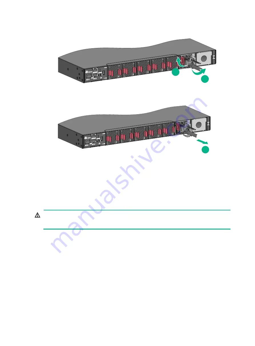
Figure2-46 Opening the cable clamp 


Figure2-47 Removing the power cord from the power module 


3. 

Hold the handle of the power module with one hand, press the latch on the power module to the 
right with your thumb, and pull the power module part way out of the slot. Supporting the power 
module bottom with one hand, slowly pull the power module out of the slot along the guide rails 
with the other. 

Place the removed power module in an antistatic bag. 

Connecting the power cord 


WARNING! 

Provide a circuit breaker for each power input. When you connect a power cord, make sure the 
circuit breaker is switched off. 


Connecting the power cord for an 
LSVM1AC300/LSVM1AC650/PSR250-12A/PSR250-12A1/P
SR450-12A/PSR450-12A1 power module 

1. 

Insert the female connector of the power cord supplied with the power module into the power 
receptacle on the power module.


2. 

Use a cable tie to secure the power cord to the handle of the power module, as shown in 

Figure2-48

.


3. 

Connect the other end of the power cord to a power source.


1

2

3

Summary of Contents for S6800 Series

Page 1: ...is manual may be reproduced or transmitted in any form or by any means without prior written consent of New H3C Technologies Co Ltd Except for the trademarks of New H3C Technologies Co Ltd any tradema...

Page 2: ...for an LSVM1DC300 LSVM1DC650 power module 34 Connecting the power cord for a PSR450 12AHD power module 35 Connecting the power cord for a PSR450 12D power module 36 Installing and removing an expansio...

Page 3: ...ii Fan tray failure 52 Configuration terminal issues 52 No display on the configuration terminal 53 Garbled display on the configuration terminal 53...

Page 4: ...QF H3 LS 6800 54QF H5 S6800 54QT LS 6800 54QT LS 6800 54QT H1 LS 6800 54QT H3 S6800 54HF LS 6800 54HF S6800 54HT LS 6800 54HT S6800 2C LS 6800 2C LS 6800 2C H1 S6800 2C FC LS 6800 2C H1 FC S6800 4C LS...

Page 5: ...the required range To avoid electrical shocks do not open the chassis while the switch is operating or when the switch is just powered off When replacing FRUs including power modules fan trays and ex...

Page 6: ...contact points In the worst case electrostatic adsorption can cause communication failure Table1 2 Dust concentration limits in the equipment room Substance Particle diameter Concentration limit Dust...

Page 7: ...netic shielding for example shielded interface cables when necessary To prevent signal ports from getting damaged by overvoltage or overcurrent caused by lightning strikes route interface cables only...

Page 8: ...reby Figure2 1 Hardware installation flow Ground the switch Install the switch Start Connect the power cords Verify the installation Switch on the circuit breakers to power on the switch Operating cor...

Page 9: ...air of slide rails optional See Figure2 7 S6800 32Q 1U high one pair provided See Figure2 2 1U high including one pair of chassis rails and one pair of slide rails provided See Figure2 7 S6800 54QT LS...

Page 10: ...6800 54QF H3 S6800 54QF LS 6800 54QF H5 and S6800 54QT LS 6800 54QT H3 switches Figure2 4 Mounting brackets for the S6800 2C and S6800 2C FC switches Figure2 5 Mounting brackets for the S6800 4C switc...

Page 11: ...and super short slide rail 1 Chassis rail 2 Super short slide rail Figure2 7 1U chassis rail and slide rail 1 Chassis rail 2 Slide rail Figure2 8 1U chassis rail and long slide rail 1 Chassis rail 2...

Page 12: ...ssis dimensions Distance between the front and rear rack posts Rack requirements S6800 32Q Using mounting brackets chassis rails and slide rails Height 43 6 mm 1 72 in 1 RU Width 440 mm 17 32 in Depth...

Page 13: ...Depth 426 mm 16 77 in 26 mm 1 02 in for the power module fan tray handle 400 mm 15 75 in for the chassis 621 to 793 mm 24 45 to 31 22 in A minimum of 600 mm 23 62 in in depth recommended A minimum of...

Page 14: ...for the power module fan tray handle 460 mm 18 11 in for the chassis 621 to 854 mm 24 45 to 33 62 in A minimum of 800 mm 31 50 in in depth recommended A minimum of 130 mm 5 12 in between the front ra...

Page 15: ...9 mm 20 47 to 30 28 in S6800 4C Using mounting brackets installed at the port side chassis rails and slide rails Height 88 1 mm 3 47 in 2 RU Width 440 mm 17 32 in Depth 776 mm 30 55 in 26 mm 1 02 in f...

Page 16: ...and LS 6800 54QF H5 S6800 54QT LS 6800 54QT H3 S6800 54HF S6800 54HT S6800 2C and S6800 2C FC switches each provide two grounding points primary grounding point with a grounding sign and auxiliary gro...

Page 17: ...mounting position 2 Primary grounding point 3 Auxiliary grounding point 1 4 Port side mounting position Figure2 14 Mounting and grounding positions on the S6800 54QT LS 6800 54QT H3 switch 1 Power mod...

Page 18: ...to the chassis To install the mounting brackets at the power module side see Figure2 16 Figure2 17 and Figure2 18 To install the mounting brackets at the port side see Figure2 19 Figure2 20 Figure2 21...

Page 19: ...r the mounting brackets Figure2 17 Attaching the mounting brackets and chassis rails to an S6800 2C S6800 2C FC switch power module side mounting position for the mounting brackets Figure2 18 Attachin...

Page 20: ...ng the mounting brackets and chassis rails to an S6800 54QF LS 6800 54QF H3 and LS 6800 54QF H5 switch port side mounting position for the mounting brackets Figure2 21 Attaching the mounting brackets...

Page 21: ...side mounting position for the mounting brackets Figure2 23 Attaching the mounting brackets and chassis rails to an S6800 54QT LS 6800 54QT H3 switch port side mounting position for the mounting brac...

Page 22: ...side use the grounding point near the power modules The S6800 32Q S6800 54QF LS 6800 54QF and LS 6800 54QF H1 S6800 54QT LS 6800 54QT and LS 6800 54QT H1 and S6800 4C switches each provide three groun...

Page 23: ...rails to the rack 1 Identify the rack attachment position for the slide rails 2 Install cage nuts user supplied in the mounting holes in the rack posts 3 Align the screw holes in one slide rail with t...

Page 24: ...sis rails with the slide rails on the rack posts b Pushes the switch slowly to slide the chassis rails along the slide rails until the mounting brackets are flush with the rack posts 6 The other perso...

Page 25: ...29 Mounting the S6800 2C switch in the rack power module side mounting position for the mounting brackets Figure2 30 Mounting the S6800 2C switch in the rack port side mounting position for the mounti...

Page 26: ...31 Mounting the S6800 4C switch in the rack power module side mounting position for the mounting brackets Figure2 32 Mounting the S6800 4C switch in the rack port side mounting position for the mounti...

Page 27: ...f the switch has a noise filter whose central ground is directly connected to the chassis to form the chassis ground commonly known as PGND You must securely connect this chassis ground to the earth s...

Page 28: ...ray fail during the switch operation replace the faulty fan trays one by one and finish replacing a fan tray within three minutes Installing a fan tray CAUTION To prevent damage to the fan tray or the...

Page 29: ...nd slide the fan tray along the guide rails into the slot until the fan tray is fully seated in the slot and has a firm contact with the backplane Figure2 35 Installing an LSWM1BFANSC fan tray Install...

Page 30: ...s good skin contact and is reliably grounded 2 Loosen the captive screw of the fan tray with a Phillips screwdriver until it is fully disengaged from the switch chassis 3 Grasp the handle of the fan t...

Page 31: ...the removed fan tray in an antistatic bag Figure2 38 Removing an LSPM1FANSA fan tray Installing and removing a power module WARNING In power redundancy mode you can replace a power module without powe...

Page 32: ...age to the connectors inside the switch chassis insert the power module gently If you encounter a hard resistance while inserting the power module pull out the power module and insert it again As a be...

Page 33: ...removing one or two power modules does not affect the operation of the switch When the switch has only two power module installed removing a power module might power off the switch or cause power insu...

Page 34: ...humb and forefinger and pull the connector out of the power module See Figure2 44 For a PSR450 12D power module use a flat head screwdriver to loosen the screws on the power cord connector and then pu...

Page 35: ...n the power cord connector 2 Pull the power cord connector out Removing a PSR450 12AHD power module The PSR450 12AHD power module removal procedure is the same for the S6800 54QF LS 6800 54QF H3 S6800...

Page 36: ...removed power module in an antistatic bag Connecting the power cord WARNING Provide a circuit breaker for each power input When you connect a power cord make sure the circuit breaker is switched off C...

Page 37: ...r receptacle on the power module and insert the plug into the receptacle The receptacle is foolproof If you cannot insert the plug into the receptacle re orient the plug rather than use excessive forc...

Page 38: ...or 12 AWG 5 3 mm 2 or 10 AWG Connecting the power cord for a PSR450 12AHD power module 1 Slide the cable clamp onto the tie mount on the power module as shown in Figure2 50 2 Connect the female connec...

Page 39: ...53 3 Connect the other end of the power cord to a DC power source Figure2 53 Connecting the DC power cord for a PSR450 12D power module If the provided DC power cord cannot meet your connection requi...

Page 40: ...ation and removal procedures are the same This section uses the LSWM18QC interface module as an example Installing an expansion module 1 Wear an ESD wrist strap and make sure the wrist strap makes goo...

Page 41: ...able damage If you are not to install a new expansion module after removing the original one install the filler panel in the slot to prevent dust and ensure good ventilation in the device To remove an...

Page 42: ...ation verify that There is enough space for heat dissipation around the switch and the rack is stable The grounding cable is securely connected The correct power source is used The power cords are cor...

Page 43: ...i console cable Do not use the two ways together on the same S6800 switch The example uses a console cable to connect a console terminal PC to the serial console port on the switch Figure3 1 Connectin...

Page 44: ...l ports on PCs do not support hot swapping If the switch has been powered on connect the serial console cable to the PC before connecting to the switch and when you disconnect the cable first disconne...

Page 45: ...42 Figure3 3 Device Driver Installation Wizard 6 Click Continue Anyway if the following dialog box appears Figure3 4 Software Installation 7 Click Finish...

Page 46: ...minal emulator programs see the user guides for these programs The following are the required terminal settings Bits per second 9600 Data bits 8 Stop bits 1 Parity None Flow control None Powering on t...

Page 47: ...options differ with software versions For more information about Boot ROM menu options see the software matching release notes for the device After the startup completes you can access the CLI to conf...

Page 48: ...54QF H3 and LS 6800 54QF H5 S6800 54QT LS 6800 54QT H1 and LS 6800 54QT H3 S6800 2C LS 6800 2C H1 and S6800 4C LS 6800 4C H1 S6800 32Q LS 6800 32Q S6800 2C LS 6800 2C S6800 4C LS 6800 4C S6800 54QF L...

Page 49: ...d identify the number of required IRF member switches depending on the user density and upstream bandwidth requirements The switching capacity of an IRF fabric equals the total switching capacities of...

Page 50: ...hout interrupting network services You connect the IRF member switches through IRF ports the logical interfaces for the connections between IRF member switches Each IRF member switch has two IRF ports...

Page 51: ...the 10GBase T Ethernet ports SFP ports QSFP ports and QSFP28 ports on the S6800 switch can be used for IRF connections When you use QSFP cables to connect physical IRF ports follow these guidelines M...

Page 52: ...ers The switches in the ring topology see Figure4 5 are in the same order as connected in the rack Figure4 4 Connecting the switches in one rack Figure4 5 IRF fabric topology Connecting the IRF member...

Page 53: ...ation Guide depending on the software version Connecting the physical IRF ports CAUTION Wear an ESD wrist strap when you connect cables or transceiver modules and optical fibers For more information s...

Page 54: ...ology information display irf topology NOTE To avoid IP address collision and network problems configure at least one multi active detection MAD mechanism to detect the presence of multiple identical...

Page 55: ...LSWM1BFANSC LSWM1BFANSC SN LSWM1BFANSCB or LSWM1BFANSCB SN fan tray is faulty the Alarm LED on the fan tray is steady yellow and the system outputs alarm messages When an LSPM1FANSA LSPM1FANSA SN LSP...

Page 56: ...cable 3 Verify that the following settings are configured for the terminal Baud rate 9600 Data bits 8 Stop bits 1 Parity None Flow control None 4 If the issue persists contact H3C Support Garbled dis...

Reviews: