


56
Layer 3 static aggregation configuration example
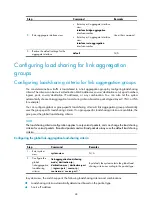
Network requirements
As shown in
:
•
Device A and Device B are connected by their Layer 3 Ethernet interfaces Ethernet 1/0/1 through
Ethernet 1/0/3.
•
Configure a Layer 3 static aggregation group on both Device A and Device B. Configure IP
addresses and subnet masks for the corresponding Layer 3 aggregate interfaces.
•
Enable traffic to be load-shared across aggregation group member ports based on source and
destination IP addresses.
Figure 16
Network diagram
Configuration procedure
1.
Configure Device A:
# Create Layer 3 aggregate interface Route-Aggregation 1, and configure an IP address and
subnet mask for the aggregate interface.
<DeviceA> system-view
[DeviceA] interface route-aggregation 1
[DeviceA-Route-Aggregation1] ip address 192.168.1.1 24
[DeviceA-Route-Aggregation1] quit
# Assign Layer 3 Ethernet interfaces Ethernet 1/0/1 through Ethernet 1/0/3 to aggregation
group 1.
[DeviceA] interface ethernet 1/0/1
[DeviceA-Ethernet1/0/1] port link-aggregation group 1
[DeviceA-Ethernet1/0/1] quit
[DeviceA] interface ethernet 1/0/2
[DeviceA-Ethernet1/0/2] port link-aggregation group 1
[DeviceA-Ethernet1/0/2] quit
[DeviceA] interface ethernet 1/0/3
[DeviceA-Ethernet1/0/3] port link-aggregation group 1
[DeviceA-Ethernet1/0/3] quit
# Configure the global link-aggregation load-sharing criteria as the source and destination IP
addresses of packets.
[DeviceA] link-aggregation load-sharing mode source-ip destination-ip
2.
Configure Device B in the same way as you configure Device A.
3.
Verify the configurations:
# Display summary information about all aggregation groups on Device A.
[DeviceA] display link-aggregation summary
Aggregation Interface Type:
BAGG -- Bridge-Aggregation, RAGG -- Route-Aggregation


