background image


12 

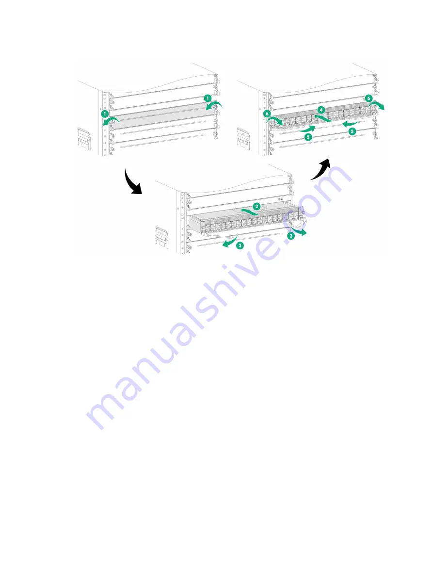
Figure 3-6 Installing an interface module 


Installing fabric modules 

The device comes with all fabric module slots empty. Purchase fabric modules and filler panels for 
the device as required. 

Installing fabric modules 

Follow these restrictions and guidelines when you install fabric modules: 


When you install a fabric module, avoid damaging the connectors on it. 


Fan trays cover fabric module slots as follows. Before installing a fan tray, install fabric 
modules or filler panels in the fabric module slots that the fan tray will cover. 


FAN1

—Fabric module slots 20 and 21. 


FAN2

—Fabric module slots 22 and 23. 


FAN3

—Fabric module slots 24 and 25. 


FAN4

—Fabric module slots 26 and 27. 


FAN5

—Fabric module slot 28. 


Slots 20, 21, and 28 can be empty without a fabric module or filler panel installed. If you are not 
to install a fabric module in slot 22, 23, 24, 25, 26, or 27, install a filler panel. 


To use S12500R interface modules on the device, install fabric modules in slots 22 to 27. The 
S12500R interface modules cannot start up if no fabric modules are installed in the six slots. 


If you want to install or replace fabric modules under two fan trays when the device is operating, 
perform the following steps: 

a. 

Remove a fan tray and install or replace the fabric modules. 

b. 

Reinstall the fan tray. 

Summary of Contents for S12516CR

Page 1: ...H3C S12516CR Switch Router Installation Quick Start New H3C Technologies Co Ltd http www h3c com Document version 5PW100 20200731...

Page 2: ...espective owners Notice The information in this document is subject to change without notice All contents in this document including statements information and recommendations are believed to be accur...

Page 3: ...1 Installing fabric modules 12 Installing fabric modules 12 Installing a filler panel in a fabric module slot 15 Removing a filler panel from a fabric module slot 17 Installing fan trays 18 Installing...

Page 4: ...vice must be used indoors To make sure the device operates correctly and to prolong its service lifetime the installation site must meet the load bearing temperature humidity cleanness EMI grounding p...

Page 5: ...2 2 Installing the device Device dimensions Figure 2 1 Device dimensions 1 Top hood 2 Mounting bracket...

Page 6: ...rails have an adjustment range of 630 mm 24 80 in to 900 mm 35 43 in and occupy 1U rack space For information about installing the LSXM1BSR slide rails see H3C LSXM1BSR 1U Bottom Support Rails Instal...

Page 7: ...ily injury follow these guidelines to lift and move the device Use the chassis handles rather than the handles of the components fan trays power supplies and modules as well as the chassis air vents t...

Page 8: ...go of your hands immediately because this might tip the device damaging the device or even causing bodily injury 4 Use M6 screws provided with the device to secure the mounting brackets to the rack po...

Page 9: ...s NEBS compliant Connect the two hole grounding lug of the grounding cable to the chassis and the ring terminal to a grounding strip To ground the device 1 Unpack the grounding cable 2 Use a screwdriv...

Page 10: ...entilation of the device install filler panels in the unused module slots and power supply slots Attaching an ESD wrist strap To prevent electronic components from ESD damage wear an ESD wrist strap w...

Page 11: ...th the lettering facing upward and then position the cable management bracket near its installation position on the mounting bracket 3 Align the captive screws on the cable management bracket with the...

Page 12: ...ller panel from the target SEU slot Keep the removed filler panel secure for future use 2 As shown by callout 2 in Figure 3 3 hold both sides of the SEU with two hands and insert the SEU into the slot...

Page 13: ...er Slowly pull the environment management module out of the slot 2 Unpack a new environment management module 3 Press the latch on the new module rightwards to release the ejector lever and then fully...

Page 14: ...and the ejector lever pillow blocks on the interface module slots have purple marks To install an interface module 1 As shown by callout 1 in Figure 3 6 remove the filler panel from the target interfa...

Page 15: ...Fabric module slots 20 and 21 FAN2 Fabric module slots 22 and 23 FAN3 Fabric module slots 24 and 25 FAN4 Fabric module slots 26 and 27 FAN5 Fabric module slot 28 Slots 20 21 and 28 can be empty withou...

Page 16: ...or 2 Remove the protection box from the connector side of the fabric module For information about removing the protection box see Figure 3 8 3 Release the ejector levers by pressing the spring clips 4...

Page 17: ...r 1 Air deflector 2 Close the air deflector until it is locked in place Figure 3 8 Removing the protection box 1 Loosen the captive screws on the protection box 2 Hold the protection box to disengage...

Page 18: ...15 Figure 3 9 Installing a fabric module Installing a filler panel in a fabric module slot 1 Loosen the captive screws on the ejector levers and rotate outward the ejector levers...

Page 19: ...rails See callout 1 in Figure 3 10 Keep the filler panel parallel to the fabric module slot to avoid touching other components in the chassis 3 As shown by callout 2 in Figure 3 10 continue to push th...

Page 20: ...lout 2 in Figure 3 11 rotate outward the ejector levers Then pull the filler panel part way out of the slot 3 As shown by callout 3 in Figure 3 11 hold the filler panel by the top and bottom edges to...

Page 21: ...swap a fan tray the remaining fan tray automatically increases the rotation speed and makes louder noise Take protection measures such as wearing an earmuff or earplug Long time exposure to strong ai...

Page 22: ...tray slot The device comes with the FAN1 and FAN5 slots installed with filler panels To install a fan tray in the FAN1 or FAN5 slot or install a fabric module in slot 20 or 21 under the FAN 1 slot or...

Page 23: ...3 loosen the M3 screws on the fan tray filler panel 2 As shown by callout 2 in Figure 3 13 put your fingers into the holes of the filler panel and then pull the filler panel out Keep the removed fille...

Page 24: ...PWR 1 PWR 2 PWR 3 PWR 5 PWR 6 PWR 4 PWR 1 PWR 2 PWR 3 PWR 5 PWR 6 PWR 4 PWR 1 PWR 2 PWR 3 PWR 5 PWR 6 Power input 1 Power input 2 Power input 3 Power input 4 Power input 5 Power input 6 Power input 1...

Page 25: ...r supply in place as shown in Figure 3 16 Figure 3 16 Installing a power supply Connecting power cords WARNING Make sure each power cord has a separate circuit breaker Before connecting a power cord p...

Page 26: ...Release the tab on the tie mount and then slide the cable clamp forward until it is flush against the edge of the connector as shown by callout 2 in Figure 3 18 3 Close the cable clamp as shown by ca...

Page 27: ...use a Phillips screwdriver to fasten the captive screws Optional Installing power trays The device comes with four power trays installed You can install more power trays on it To install a power tray...

Page 28: ...25 Figure 3 21 Removing a front filler panel from a power tray slot Figure 3 22 Removing a rear filler panel from a power tray slot...

Page 29: ...p hood installed You only need to install the air filter in the top hood To install the air filter in the top hood 1 Unpack the air filter 2 Position the air filter over the top hood and then push the...

Page 30: ...t caps for the fiber connector Installing a transceiver module The transceiver modules are hot swappable To install a transceiver module 1 Unpack the transceiver module Do not touch the golden plating...

Page 31: ...cable is no less than eight times the cable diameter The interface cables are hot swappable To connect an interface cable 1 Unpack the interface cable 2 Correctly orient the interface cable connector...

Page 32: ...mendations The cable management brackets are installed at the two sides of the chassis front panel As a best practice route network cables from the left and right sides as shown in Figure 4 1 Figure 4...

Page 33: ...e cable to the serial port of the PC 2 Plug the RJ 45 connector of the console cable to the console port of the device Figure 5 1 Connecting a terminal to the console port Verification before login Be...

Page 34: ...ing Normal Extended BootWare The Extended BootWare is self decompressing Done System image is starting Line aux0 is available Press ENTER to get started Press Enter at the prompt When the prompt Sysna...

Reviews: