background image


14 

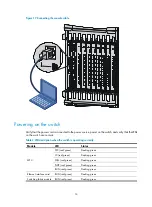
Figure 19


Connecting the console cable 


Powering on the switch 

Verify that the power cord is connected to the power source, power on the switch, and verify that the LEDs 

on the switch are normal. 

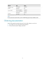
Table 2


LED description when the switch is operating correctly 

Module LED 

Status 

MPU 

SFC (red/green) 

Flashing green 

LC (red/green) 

Flashing green 

FAN (red/green) 

Flashing green 

PWR (red/green) 

Flashing green 

RUN (red/green) 

Flashing green 

Ethernet interface card 

RUN (red/green) 

Flashing green 

Switching fabric module  RUN (red/green) 

Flashing green 

Summary of Contents for S12500 Series

Page 1: ...H3C S12500 Routing Switch Series Quick Installation Guide Hangzhou H3C Technologies Co Ltd http www h3c com Document version APW201 20131030...

Page 2: ...ll other trademarks that may be mentioned in this manual are the property of their respective owners Notice The information in this document is subject to change without notice Every effort has been m...

Page 3: ...the switch 2 Removing the power frame mounting bracket 3 Installing the switch in a rack 3 Grounding the switch 5 Installing the power modules 5 Installing a fan tray 6 Installing a card 7 Connecting...

Page 4: ...es see H3C S12500 Routing Switch Series Installation Guide Preparing for installation ESD prevention To prevent the electronic components from being damaged by the electrostatic discharge ESD always w...

Page 5: ...ule and space requirements For more information see H3C S12500 Routing Switch Series Installation Guide Installation tools and accessories Installing the switch Figure 2 Installation flow Phillips scr...

Page 6: ...n Before installation make sure the bottom edge of the slide rails or rack shelf aligns with the middle of the narrower metal area between holes Figure 4 Installing the slide rails 1 Middle of the nar...

Page 7: ...install cage nuts to all the marked positions on the right rack post Figure 5 Installing the cage nuts Mounting the switch in the rack 1 Use several people to place the switch on the slide rails or r...

Page 8: ...he grounding cable Installing the power modules AC and DC power modules are installed in the same way To install a power module 1 Rotate the power frame panel up with both hands 2 Pull the clip at the...

Page 9: ...e power frame panel on an S12508 Installing a fan tray Each of the S12508 and the S12518 has two fan trays They are installed in the same way To install a fan tray 1 Remove the blank panel from the sl...

Page 10: ...stalling a fan tray for the S12508 Installing a card Slot requirements Install MPUs LPUs and switching fabric modules into appropriate slots as shown in Figure 12 NOTE On an S12508 or S12518 switch in...

Page 11: ...nstalling a card This section describes how to install an MPU as an example To install an MPU 1 Remove the protective cover before installing an MPU Put on an ESD wrist strap and then loosen the capti...

Page 12: ...r levers on the front panel of the MPU outwards hold up the MPU by one hand without touching any electronic components on the MPU and hold the front panel by the other hand to push the MPU into the sl...

Page 13: ...he switch Connecting an AC power cord CAUTION Typically 10 A busbars are available in the equipment room but the AC power supply system requires a 16 A power cord AC so you need to use a 16 A busbar a...

Page 14: ...of the AC power cord to the power source Figure 16 Connecting the AC power cord Connecting a DC power cord WARNING A plastic protection cover is installed in front of the grounding strip to protect o...

Page 15: ...d of the black DC power cord to the RTN terminal that provides power to the switch 4 Put the protection cover on the wiring terminals Figure 18 Installing the protection cover Verifying the installati...

Page 16: ...ic modules are correctly installed and have close contact with the backplane Logging in to the switch IMPORTANT You can only log in through the console port for your first login to the switch Connecti...

Page 17: ...LEDs on the switch are normal Table 2 LED description when the switch is operating correctly Module LED Status MPU SFC red green Flashing green LC red green Flashing green FAN red green Flashing green...

Page 18: ...Fan tray RUN green Flashing ALM red Off NOTE For more information about the LEDs see H3C S12500 Routing Switch Series Installation Guide Obtaining documentation Take the following steps to get related...

Page 19: ...tools and accessories 2 Installing a card 7 Installing a fan tray 6 Installing the power modules 5 Installing the switch in a rack 3 P Powering on the switch 14 R Removing the power frame mounting bra...

Reviews: