background image

44 

INSTALLATION INSTRUCTIONS 

The installation is the exclusive responsibility of specialists.  
The user of this appliance is held to respect the legislation and the standards enforced in his 
home country. 

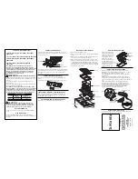
How to stick the gasket: 


Fitting - installing: 

  The dimensions are:  


Cut size 

Flush mounting 

Glass size 

Type 

Width 

Depth 

Width 

Depth 

Radius 

Width 

Depth 

Thickness 

11T581I 

547 

486 

586 

516 

580 

510 


  Ensure that there is a distance of 50 mm between the hob and the wall or sides. 

  The hobs are classified as “Y” class for heat protection. Ideally the hob should be installed 

with plenty of space on either side. There may be a wall at the rear and tall units or a wall 
at  one  side.  On  the  other  side,  however,  no  unit  or  device  can  be  higher  than  the 
hob.
 

  The piece of furniture or the support in which the hob is to be fitted, as well as the edges of 

furniture,  the  laminate  coatings  and  the  glue  used  to  fix  them,  must  be  able  to  resist 
temperatures of up to 100 °C. 

  The mural rods of edge must be heat-resisting. 

  Do not install the hob to the top of a non- ventilated oven or a dishwasher. 

  To ensure good air circulation of the electronic device, maintain a space of 20 mm under 

the bottom of the hob casing. 

  If a drawer is placed under the work, avoid putting flammable objects in this drawer 


(for example: sprays) or non-heat-resistant objects. 

  Materials which are often used to make worktops expand on contact with water. To protect 

the cutout edge, apply a coat of varnish or special sealant. Particular care must be given 
when  applying  the  adhesive  joint  supplied  with  the  hob  to  prevent  any  leakage  into  the 
supporting furniture. This gasket guaranties a correct seal when used in conjunction with 
smooth work top surfaces. 

  The  safety  gap  between  the  hob  and  the  cooker  hood  placed  above  must  respect  the 

indications of the hood manufacturer. Respect a distance of at least 760 mm if you do not 
have further instructions. 

  The  connecting  cable cannot  be  subjected  to  mechanical  constraint  (e.g.  a  drawer)  after 

construction. 

  WARNING: Use only hob guards designed by the manufacturer of the cooking appliance 

or indicated by the manufacturer of the appliance in the instructions for use as suitable or 
hob  guards  incorporated  in  the  appliance.  The  use  of  inappropriate  guards  can  cause 
accidents. 

Stick the gasket (2) two millimetres 

from the external edge of the glass, 

after removing the protection sheet (3). 

Summary of Contents for 11T581I

Page 1: ...GEBRAUCHSANWEISUNG NOTICE D UTILISATION INSTRUCTION MANUAL 11T581I ...

Page 2: ......

Page 3: ...ESCHREIBUNG 7 TECHNISCHE BESCHREIBUNG 7 BEDIENFELD 7 BEDIENUNG DES KOCHFELDES 7 ANZEIGE 7 BELÜFTUNG 8 INBETRIEBNAHME DES KOCHFELDES 8 VOR DEM ERSTEN AUFHEIZEN 8 INDUKTIONSPRINZIP 8 FUNKTION DER SENSOREN SCHALTFELDER 8 SLIDER FUNKTION UND ZEITSCHALTUHR 8 EIN UND AUSSCHALTEN DES KOCHFELDES 9 RESTWÄRME ANZEIGE 10 ZEITSCHALTUHR 10 PAUSEN FUNKTION 11 MEMORY FUNKTION 11 BRÜCKE FUNKTION 11 KINDERSICHERUN...

Page 4: ...Aufkleber vom Glas entfernen Es dürfen keine Änderungen an dem Gerät vorgenommen werden Verwenden Sie das Kochfeld nicht als Arbeits oder Abstellfläche Die Sicherheit ist nur gewährleistet wenn das Gerät mit einem Schutzleiter verbunden ist der den gültigen Vorschriften entspricht Der Anschluss des Gerätes an das Stromnetz darf nicht über ein Verlängerungskabel erfolgen Das Gerät darf nicht über e...

Page 5: ...hfläche nie mit einem Lappen oder einer Schutzfolie diese könnten sehr heiß werden und Feuer fangen Dieses Gerät kann von Kindern ab 8 Jahren sowie Personen mit verringerten physischen sensorischen oder mentalen Fähigkeiten oder Mangel an Erfahrung und Wissen benutzt werden wenn sie beaufsichtigt oder bezüglich des sicheren Gebrauchs des Gerätes unterwiesen wurden und die daraus resultierenden Gef...

Page 6: ...che Sprünge oder Risse auf dem Glas auftreten schalten Sie das Kochfeld bitte sofort aus schrauben die Sicherung des Kochfeldes ab und wenden Sie sich an unseren Kundendienst oder Ihren Fachhändler Reparaturen am Gerät dürfen nur von Fachkräften durchgeführt werden Öffnen Sie das Gerät auf keinen Fall selbst WARNUNG Wenn die Glasoberfläche gesprungen ist ist das Gerät auszuschalten um die Gefahr e...

Page 7: ...e Einstellung der Leistung C Reinigungsfunktion Funktion ist aktiviert E Fehleranzeige Fehler der Elektronik H Restwärme Kochzone ist heiß II Stop Go Pausen Funktion Slider Funktion und Zeitschaltuhr Rückseite Grillfläche Slider Funktion und Zeitschaltuhr Vorderseite Grillfläche Taste Reinigung Ein Aus Taste Verriegelung Anzeige Zeitschaltuhr Anzeige Leistung Anzeige Brücke Anzeige Zeitschaltuhr T...

Page 8: ...ule Wenn die Kochzone eingeschaltet wird erzeugt diese Spule ein Magnetfeld Das Magnetfeld induziert in der Kochzone Wirbelströme Dadurch erhitzt sich die Kochzone Funktion der Sensoren Schaltfelder Das Kochfeld wird über Sensortasten gesteuert Diese reagieren auf leichte Berührungen des Glases mit dem Finger Wenn Sie die Tasten etwa eine Sekunde lang berühren werden die Steuerbefehle ausgeführt J...

Page 9: ...en über den SLIDER bis zu 0 streichen 0 oder H Erfolgt keine weitere Eingabe schaltet sich das Kochfeld aus Sicherheitsgründen nach ca 20 Sekunden aus und die Anzeige erlischt Beispiel Leistungserhöhung Die Leistungsstufen leuchten nacheinander auf bis die gewünschte Leistung erreicht ist Beispiel für Reduzierung der Leistung Die Leistungsstufen erlöschen nach und nach bis die gewünschte Leistung ...

Page 10: ... aktiviert und der Zeitablauf beginnt Zeitschaltuhr ausschalten Betätigung Bedienfeld Anzeige Zeitschaltuhr auswählen Gleichzeitig und der Die Anzeige Zeitschaltuhr betätigen bis die der ausgewählten gewünschte Kochzone erreicht ist Kochzone leuchtet auf Zeitschaltuhr ausschalten betätigen 000 Wenn mehrere Zeitschaltuhren in Betrieb sind wiederholen Sie den Vorgang Zeitschaltuhr als Eieruhr Die Ze...

Page 11: ...evor die Anzeige zu blinken aufhört ca 6 Sekunden Die Werte der letzten Einstellungen sind nun wieder aktiviert Brücke Funktion Diese Funktion erlaubt die Koppelung von zwei Kochzonen zu einer großen Kochfläche In diesem Vorgang kann die Booster Funktion nicht aktiviert werden Betätigung Bedienfeld Anzeige Einschalten des Kochfeldes 0 I betätigen 0 Brücke einschalten Gleichzeitig clean der 0 und b...

Page 12: ... 0 I betätigen oder über den SLIDER fahren 0 bis 9 oder H Sie können auch auf den Leistungsstufen 4 5 oder 5 reinigen KOCHEMPFEHLUNGEN Einstellung der Leistung Temperatur Leistung Temperatur C 1 50 2 75 3 100 4 125 5 150 6 170 7 190 8 205 9 220 Die Speisen können direkt auf der Heizfläche mit oder ohne Fett zubereitet werden Sollten Sie Öl oder Fett verwenden ist unsere Empfehlung die Anzeige Rauc...

Page 13: ...tzmittel Spülen Sie danach die Oberfläche mit kaltem Wasser klar und reiben Sie das Kochfeld mit einem sauberen Tuch in Schleifrichtung trocken Warmreinigung betätigen Sie die Taste clean und warten Sie bis die Anzeige C nicht mehr blinkt siehe Kapitel Reinigungsfunktion Legen Sie einzelne Eiswürfel auf die Grillplatte Lösen Sie den Schmutz gleichzeitig mit der Wendeschaufel und schieben sie ihn i...

Page 14: ...iter läuft Das ist keine Störung das Gebläse läuft so lange bis das Gerät abgekühlt ist Das Gebläse schaltet automatisch ab Die Anzeige C erscheint Siehe Kapitel Reinigungsfunktion Die Anzeige II erscheint Siehe Kapitel Pausen Funktion Bei der Anzeige das Symbol oder Er03 erscheint Ein Objekt oder eine Flüssigkeit überdeckt die Tasten Die Anzeige erlischt sobald die Tasten losgelassen oder gereini...

Page 15: ...eitig an nebenstehende Hochschränken oder Wänden eingebaut werden Auf der anderen Seite dürfen Möbel oder Geräte nicht höher als das Kochfeld sein Die Arbeitsflächen sowie die Wandabschlussleisten müssen aus hitzebeständigem Material sein Das Kochfeld darf nicht über Geschirrspülen Wasch oder Trockengeräten eingebaut werden oder ohne Dunstabzugshauben betrieben werden Um eine ausreichende Belüftun...

Page 16: ...hen Anschlussdaten mit denen des Netzes übereinstimmen können Sie mit Hilfe der Angaben des Typenschilds überprüfen Das Gerät muss durch Trenneinrichtungen allpolig vom Netz abgeschaltet werden können Im abgeschalteten Zustand muss ein Kontaktabstand von 3 mm vorhanden sein Als geeignete Trennvorrichtungen gelten LS Schalter Sicherungen und Schütze Die Installation muss durch Sicherungen geschützt...

Page 17: ...schen Anschlussklemme 4 und 5 an Befestigen Sie das Erdungskabel an die vorgesehene Anschlussklemme den Nullleiter an Anschlussklemme 4 oder 5 die Phase L1 an Anschlussklemme 1 und die Phase L2 an Anschlussklemme 2 Achtung Stellen Sie sicher dass die Drähte korrekt eingesteckt sind und die Schrauben fest angezogen sind Wir übernehmen keine Haftung für Zwischenfälle die durch falschen Anschluss ode...

Page 18: ...MMANDE 22 UTILISATION DE L APPAREIL 22 AFFICHAGE 22 VENTILATION 23 MISE EN ROUTE ET GESTION DE L APPAREIL 23 AVANT LA PREMIERE UTILISATION 23 PRINCIPE DE L INDUCTION 23 TOUCHES SENSITIVES 23 ZONE DE SELECTION DE PUISSANCE SLIDER ET DE REGLAGE DE LA MINUTERIE 23 MISE EN ROUTE 24 INDICATEUR DE CHALEUR RESIDUELLE 24 FONCTION MINUTERIE 25 FONCTION PAUSE 25 FONCTION RAPPEL 26 FONCTION BRIDGE 26 VERROUI...

Page 19: ... La table de cuisson ne doit pas servir de support ou de plan de travail La sécurité n est assurée que si l appareil est raccordé à une terre de protection conforme aux prescriptions en vigueur Pour le raccordement au réseau électrique n utilisez pas de rallonge L appareil ne doit pas être utilisé au dessus d un lave vaisselle ou d un sèche linge les vapeurs d eau dégagées pourraient détériorer l ...

Page 20: ... sont réduites ou dont les expériences et les connaissances sont inadaptées uniquement si elles sont surveillées formées à l utilisation de l appareil en conditions de sécurité et informées des risques susceptibles de se présenter Les enfants ne doivent pas jouer avec l appareil Le nettoyage et l entretien ne doivent pas être confiés à des enfants sans surveillance d adultes Précautions pour ne pa...

Page 21: ...reil et couper l alimentation électrique En cas de fêlure ou de fissure de la vitrocéramique il faut impérativement débrancher l appareil du réseau électrique et prévenir le service après vente Les réparations doivent être entreprises exclusivement par un personnel spécialisé N ouvrez en aucun cas l appareil vous même ATTENTION Si la surface vitrée est fissurée coupez l alimentation de l appareil ...

Page 22: ... de cuisson E Message d erreur Défaut de circuit électronique C Fonction nettoyage La fonction nettoyage est activée H Chaleur résiduelle La zone de cuisson est chaude II Pause La table est en pause Zone de sélection de puissance Slider foyer arrière Zone de sélection de puissance Slider foyer avant Touche nettoyage Touche Marche Arrêt Touche Verrouillage Touches Minuterie Affichage de la minuteri...

Page 23: ... cuisson Lorsque celle ci est enclenchée elle produit un champ électromagnétique variable qui à son tour produit des courants induits dans le fond ferro magnétique du récipient Il en résulte un échauffement du récipient placé sur la zone de chauffe Touches sensitives Votre appareil est équipé de touches sensitives permettant de commander les différentes fonctions Un effleurage de la touche active ...

Page 24: ...un au fur et à mesure de l augmentation de la température jusqu au niveau de puissance demandé Exemple de baisse de la puissance Les segments de l affichage du niveau de puissance s éteignent un par un jusqu au niveau de puissance demandé Indicateur de chaleur résiduelle Après l arrêt des zones de cuisson ou l arrêt complet de la table les zones de cuissons sont encore chaudes et sont signalées pa...

Page 25: ...ter l opération Minuterie utilisée hors cuisson La minuterie fonctionne indépendamment des foyers et se désactive dès la mise en route d une zone de chauffe Si elle est activée et que la table de cuisson est arrêtée la minuterie continue jusqu à ce que le temps imparti est écoulé Action Bandeau de commande Afficheur Activer la table de cuisson appuyer sur 0 I 0 Sélectionner la minuterie appuyer si...

Page 26: ...ouillage du bandeau de commande Pour éviter de modifier une sélection de la table de cuisson notamment dans le cadre du nettoyage de la vitre le bandeau de commande à l exception de la touche marche arrêt 0 I peut être verrouillé Action Bandeau de commande Afficheur Verrouiller la table maintenir un doigt sur voyant verrouillage allumé pendant 6s Déverrouiller la table maintenir un doigt sur voyan...

Page 27: ...la température en fonction du type de cuisson Températures maximum et point de fumée Graisses Huiles Températures max préconisée C puissance Point de fumée C Beurre 130 4 150 Graisse de porc 170 6 200 Graisse de bovin 180 6 210 Huile d olive 180 6 200 Huile de tournesol 200 7 220 Huile d arachide 200 7 235 Graisse de noix de coco 200 7 240 Conseils de cuissons Nature du plat Température C Puissanc...

Page 28: ...ontenus dans les aliments peuvent être enlevées une fois refroidies en utilisant du jus de citron Ne pas nettoyer la zone de cuisson si elle est trop chaude RISQUE DE BRULURE N utilisez pas de produits de nettoyage abrasifs qui pourraient endommager l appareil N utilisez pas d appareil à vapeur ou de produits sous pression pour l entretien de votre appareil N utilisez pas d objets qui pourraient r...

Page 29: ...8 s affiche L entrée d air du ventilateur est obstruée libérez la Le symbole U400 s affiche La table est mal connectée au réseau Vérifiez le branchement et rebranchez la table Le symbole Er47 s affiche La table est mal connectée au réseau Vérifiez le branchement et rebranchez la table PROTECTION DE L ENVIRONNEMENT Les matériaux d emballage sont écologiques et recyclables Les appareils électronique...

Page 30: ...r entre le fond du caisson de l appareil un espace de 20 mm pour assurer une bonne circulation de l air de refroidissement de l électronique Si un tiroir se trouve sous le plan de cuisson éviter d y ranger des objets inflammables par exemple spray et des objets non résistants à la chaleur L écart de sécurité entre la table de cuisson et la hotte aspirante placée au dessus d elle doit respecter les...

Page 31: ...une alimentation en 230 V 50 60 Hz Raccordez toujours le fil de terre de protection Respectez le schéma de raccordement Utilisez le câble de raccordement qui est fixé à l appareil Le fil vert jaune correspond au fil de terre le fil bleu correspond au fil neutre et le fil marron correspond au fil de phase calculé avec le coefficient de simultanéité suivant Norme EN 60 335 2 6 1990 Monophasé 230V 1P...

Page 32: ...ANCE 36 DISPLAY 36 VENTILATION 37 STARTING UP AND APPLIANCE MANAGEMENT 37 BEFORE THE FIRST USE 37 INDUCTION PRINCIPLE 37 SENSITIVE TOUCH 37 POWER SELECTION ZONE SLIDER AND TIMER SETTING ZONE 37 STARTING UP 38 RESIDUAL HEAT INDICATION 38 TIMER 39 STOP GO FUNCTION 39 RECALL FUNCTION 40 BRIDGE FUNCTION 40 CONTROL PANEL LOCKING 40 CLEAN FUNCTION 40 COOKING ADVICES 41 SETTING UP THE COOKING LEVELS TEMP...

Page 33: ...nnot be used freestanding nor can it be used as a work surface The appliance must be grounded and connected in accordance with local standards Do not use any extension cord to connect it The appliance cannot be used above a dishwasher or a tumble dryer steam may damage the electronic appliances The appliance is not intended to be operated by means of external timer or separate remote control syste...

Page 34: ...rvision Precautions not to damage the appliance Raw pan bottoms or damaged saucepans not enamelled cast iron pots may damage the ceramic glass Sand or other abrasive materials may damage ceramic glass Avoid dropping objects even little ones on the vitroceramic Do not hit the edges of the glass with a saucepan Make sure that the ventilation system of the appliance works according to the manufacture...

Page 35: ...s service Repair should be done by specialists Do not open the appliance yourself WARNING If the surface is cracked switch off the appliance to avoid the possibility of an electric shock Other protections For people with a pacemaker the magnetic field could influence its function We recommend you to retrieve further information from the retailer or the doctor Do not use aluminium or synthetic cont...

Page 36: ...eating zone is activated 1 9 Booster level Selection of the cooking level E Error message Electronic failure C Clean function Clean function is active H Residual heat The heating zone is hot II Stop Go The hob is in pause Power selection zone Slider rear zone Power selection zone Slider front zone Clean function key On Off key Locking key Timer display Pause Recal key Bridge display Timer display ...

Page 37: ...it is working it produces a variable electromagnetic field which produces inductive currents in the ferromagnetic bottom plate of the pan The result is a heating up of the pan located on the heating zone Of course the pan has to be adapted Sensitive touch Your ceramic hob is equipped with electronic controls with sensitive touch keys When your finger presses the key the corresponding command is ac...

Page 38: ...ne until the required power level is reached Example of power decrease The segments from the power display are turning off one by one until the required power level is reached Residual heat indication After the switch off of a heating zone or the complete stop of the hob the heating zones are still hot and the symbol H indicates this on the display The symbol H disappears when the heating zones ma...

Page 39: ...g timer function Egg timer is an independent function It stops as soon as a heating zone starts working When the hob is switched off the timer continues until it has reached the selected time Action Control panel Display Activate the hob press display 0 I 0 Select the Timer Press simultaneously key and 000 from the timer Decrease the time Press key from the timer 60 to 59 58 Increase the time Pres...

Page 40: ... simultaneously on clean 0 of the 2 cooking zones Control panel locking To avoid modification of the setting of the cooking zones particularly when cleaning the control panel can be locked with exception to the On Off key 0 I Action Control panel Display Lock the hob Press during 6s lock light on Unlock the hob Press during 6s lock light off Clean function The clean function guarantees a satisfact...

Page 41: ...ture in accordance with the type of cooking required Maximum temperature and smoking point Grease Oil Maximum recommended temperature C power Smoke point C Butter 130 4 150 Lard 170 6 200 Beef fat 180 6 210 Olive oil 180 6 200 Sunflower oil 200 7 220 Peanut oil 200 7 235 Coconut oil 200 7 240 Cooking advice Types of food Temperature C Power Fish and seafood 170 180 6 Veal 160 180 6 Beef 200 210 8 ...

Page 42: ... remove light marks with a spatula and push them into the drain Clean the drain with absorbent paper for example Cold water can replace the icicles Then dry the surface thoroughly with movements that follow the natural grooves of the cooking surface no circular movements with a clean rag Some marks that come from acid naturally contained in food can be cleaned with lemon juice when the appliance i...

Page 43: ...s the control keys The symbol disappear as soon as the key is released or cleaned The control panel displays E2 The hob is overheated let it cool and then turn it on again The control panel displays E8 The air inlet of the ventilator is obstructed release it The control panel displays U400 The hob is not connected to the network Check the connection and reconnect the hob The control panel displays...

Page 44: ... air circulation of the electronic device maintain a space of 20 mm under the bottom of the hob casing If a drawer is placed under the work avoid putting flammable objects in this drawer for example sprays or non heat resistant objects Materials which are often used to make worktops expand on contact with water To protect the cutout edge apply a coat of varnish or special sealant Particular care m...

Page 45: ...should always connect the earth wire Respect the connection diagram Use the connecting cable that is attached to the device The green yellow wire corresponds to the earth wire the blue wire corresponds to the neutral wire and the brown wire correspond to the phase calculé avec le coefficient de simultanéité suivant Norme EN 60 335 2 6 1990 Monophase 230V 1P N Put a bridge between terminal 1 and 2 ...

Page 46: ......

Page 47: ......

Page 48: ...18695 0 ...

Reviews: