


4.3 INSTALLING THE CONTROL UNIT
The control unit is to be fitted using a “keyhole fixture” in a suitable, moisture-
free location. Screw in two screws with a centre to centre distance of 70 mm
(see markings on the top edge of the unit). Make sure that the display and the
knob on the control unit are easy to read and to adjust. Then connect the com-
munication cable between the valve unit and the control unit. NB The communi-
cation cable between the valve unit and the control unit must be connected be-
fore the DC Transformer is plugged into a wall socket. The cable supplied is 3 metres long, but can be
replaced with a different cable of the desired length (standard network cable RJ45, max. 100 metres).
4.4 CONNECTING THE DC TRANSFORMER
Plug the adapter into a wall socket (230 V) and connect the low current contact to the control unit (24 V).
4.5 STARTING THE WATER LEAK GUARD
On initial start-up or after a factory reset, the menu will display options for setting the language, date
and time.
1. Use the knob to select the desired language, and then press the knob to confirm.
2. To set the date and time: turn the knob to choose the relevant setting “Set date” or “Set time”. Then
press the knob to activate editing mode, turn to the desired setting for the respective values, and press
again to confirm the selection.
After the water leak guard has been connected to current, it and its functions will be activated auto-
matically.
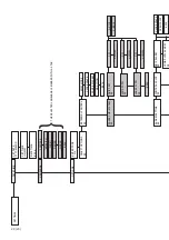
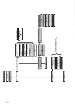
Use the menu to set the date and the time. See MENU TREE page 20.
After starting the system, we recommend performing an initial test to check that the tap water system
is not leaking.
1. Make sure that there is no flow in the tap water system by checking that all tapping points are
closed.
2. To start the initial test, select the relevant item from the menu, see MENU TREE page 19.
3. If no flows or leaks are detected during the initial test, the water leak guard will return
automatically to normal operating condition and the status “OK” will appear in the display. If the water
leak guard registers a flow or a leak, the motorised ball valve will close and an alarm will be triggered.
The initial test takes approx. 3 minutes.
For additional information, see INITIAL TEST page 12.
NB If necessary, the connection nipple (Dy22) can be replaced. Please note that the nipple and copper
seal lock the flow meter turbine in place, so it is important to tighten the replacement nipple all the
way to the bottom. When replacing with an angled connector where the thread cannot be tightened all
the way to the bottom, the copper seal must be bent so that it makes contact with both the flow meter
and the nipple. In this case, use plumbing flax to seal the nipple against the valve unit.
Delivery set-up: Nipple tightened all the
way down against the seal.
Replace nipple: Bent seal to keep the
turbine in the correct position.
11 (23)
ENGLISH
Summary of Contents for VATETTE
Page 5: ...5 23 SVENSKA ...
Page 27: ...5 23 ENGLISH ...
Page 49: ...NORSK 5 23 ...
Page 71: ...DANSK 5 23 ...
Page 93: ...5 23 SUOMI ...
Page 111: ......


