Chapter 6 Specification of Parameters
GK600 User Manual
- 228 -
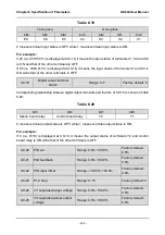
When the frequency is decreased to 0Hz by terminal UP/DOWN, the drive continues to
decrease its out frequency and change the motor rotary direction.
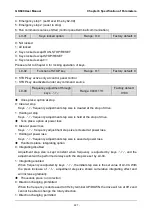
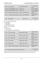
L0-04
Step size of frequency
adjustment through keys
∧
/
∨
Range:
0.00Hz/s~10.00Hz/s
Factory default:
0.03 Hz/s
When frequency setting is "digital setting + control panel
∧
/
∨
adjustment", progressive
increase and decrease of frequency setting is realized through
∧
or
∨
on control panel. This
parameter is used to set the step size of frequency adjustment through
∧
/
∨
. The step size is
defined as frequency variation per second, and the smallest step size is 0.01 Hz/s.
Group L1 Control Panel Display Setting
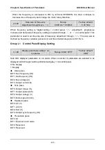
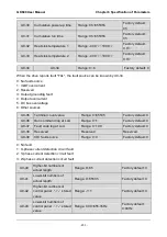
L1-00
Display parameter setting 1 on
run status
Range: 0000~3FFF
Factory default:
080F
Sets LED displayed parameters on run status. When a number of parameters are selected to be
displayed, skim-through could be performed using key >> on control panel.
0: No display
1: Display
Ones place
BIT0: Run frequency (Hz)
BIT1: Set frequency (Hz)
BIT2: Bus voltage (V)
BIT3: Output current (A)
Tens place
BIT0: Output torque (%)
BIT1: Output power (kW)
BIT2: Output voltage (V)
BIT3: Motor speed (r/min)
Hundreds place
BIT0: AI1 (V)
BIT1: AI2 (V)
BIT2: EAI (V)
BIT3: Output sync frequency (Hz)
Thousands place
BIT0: DI
BIT1: External count value
BIT2: Reserved
BIT3: Reserved

