


Exhaust Venting
This heater is designed to exhaust the products of combustion
(
fl
ue gases) to the outdoors using a sealed piping system.
Table 1 lists the allowable vent materials and sizing
information. Figure 16 shows the general venting layout
while Figures 17-19 show various end termination details and
clearances. Connection of the venting piping to the blower is
shown in Figures 21-25.
Correct installation of the venting system is essential to the
safe and ef
fi
cient operation of this water heater. Vent piping
must be installed in accordance with all applicable national and
provincial codes. All installations shall meet the requirements
as stated in the latest edition of the
"Natural Gas and
Propane Installation Codes" CSA-B149-1
.
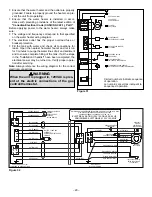
STREET ELBOW
NORMAL ELBOW
150mm
(6 in.) min.
BACK TO BACK ELBOWS
90° LONG SWEEP ELBOW
(LESS RESTRICTIVE)
90° SHORT SWEEP ELBOW
(MORE RESTRICTIVE)
PREFERRED PRACTICE
PREFERRED PRACTICES
NOT RECOMMENDED
Figure 13
Note:
The information provided in Figure 13 is intended as a
guideline for good vent installation practices only and is not
intended to restrict venting options beyond those restrictions
established by the latest edition of the
"Natural Gas and
Propane Installation Codes" CSA-B149-1
or any applicable
local and provincial codes.
High Ambient Temperature Installations
This heater requires room air to lower the
fl
ue gas temperatures
before the gases pass through the vent system. The dilution
air inlets are located on the rear of the blower assembly (see
Figures 5 & 21). As the room temperature rises, the ability
to lower the
fl
ue gases lessens so special attention to the
choice of venting material is required. Establishing the ambient
temperatures where the heater and the venting is installed is
very important, especially in regions with warmer climates or
any region that experiences hot summers. Ambient conditions
hotter than 43°C (110°F) require that the venting material be
either CPVC or polypropylene. Areas that can experience
high ambient environments include closets, alcoves, areas
under staircases, attics especially in metal roofed buildings,
areas with restricted air movement, rooms with large solar
gains, metal sheds, industrial or commercial enterprises
and venting systems exposed to direct sunlight. For high
temperature environments, obtain high limit switch upgrade
Kit # 9008306015 and use the higher rated vent piping.
Important Notes and Warnings
This heater is certified to be installed using Schedule
40 PVC or CPVC or polypropylene plastic vent material.
All jurisdictions require that this material is approved to
ULC S636. Only use approved material. All venting mate-
rial and components must be joined with the approved
primer/cleaner and solvent cement.
Do not common vent this heater with any other appli-
ance.
During operation the plastic piping will expand as it heats
up and contract as it cools down. This is normal for this
type of venting. Rigidly fastening the vent piping can
cause undue stress that may result in the cracking or
fracturing the vent piping material. A fracture of the vent-
ing pipe may pose a serious safety hazard. To prevent
stressing of the vent system, all hangers and supports
must allow the vent piping freedom to move.
Use long sweep elbows wherever possible. Closely-
coupled elbows and short radius elbows can reduce the
venting capacity.
All power vented water heaters generate a certain
amount of operational noise. In order to minimize noise
transmission to the support structure, it is recommended
to use isolation pads between the pipe hangers and the
vent pipe.
Most power vent installations develop some condensa-
tion in the vent piping. When using long runs of venting
or when the venting passes through cold or unheated
areas, considerable amounts of condensate from the flue
gases can develop. Provision must be made for the con-
densate to drain freely from the system or to be collected
in a condensate trap(s) that can be drained. Damage or
fracture of the vent piping may occur if the condensate
is allowed to collect and freeze. Pooling of condensate
can restrict airflow and can cause nuisance failures of
the system.
•
•
•
•
•
•
–
11
–


