background image

Geophysical Survey Systems, Inc. 

GS Series 


200 HS Antenna 

MN27-151 Rev A 

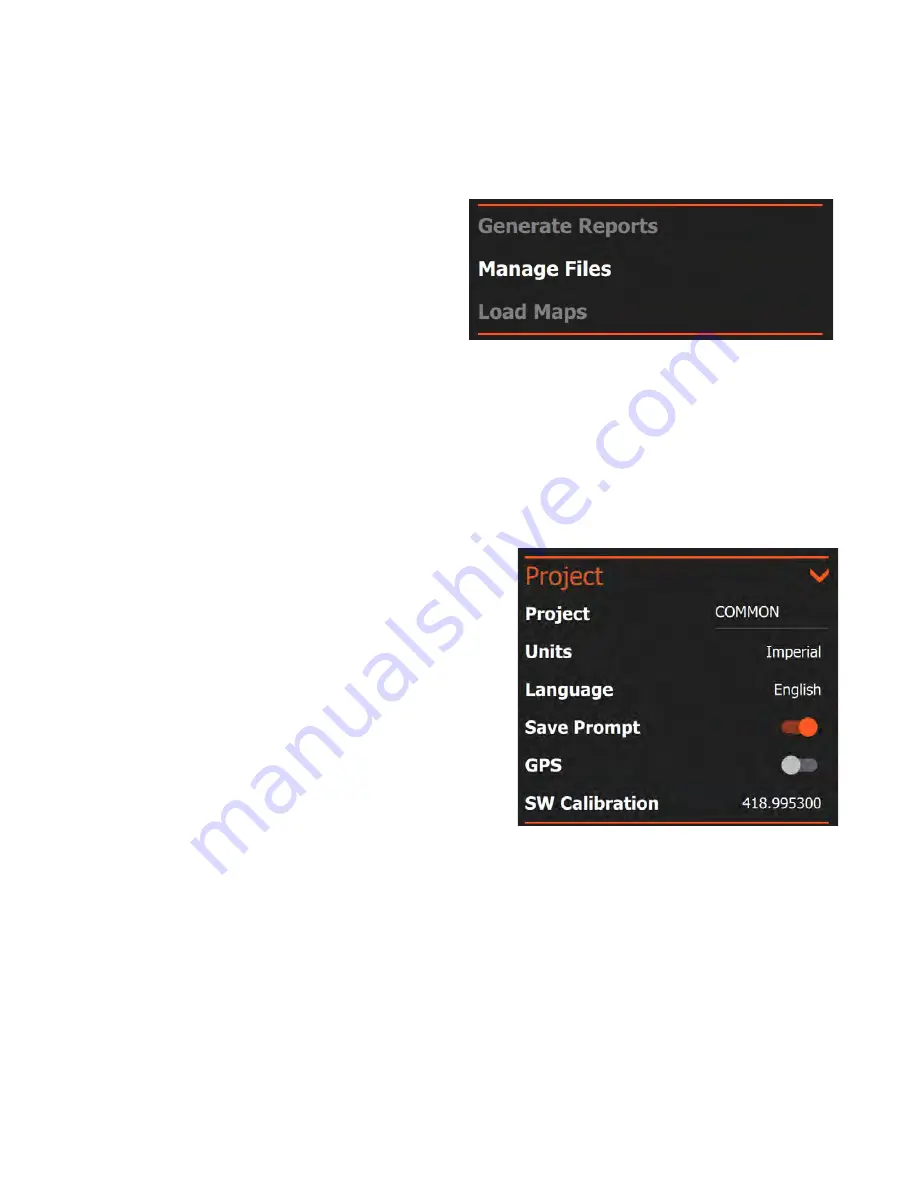
Generate Reports


This section allows you to manage reporting outputs, transfer/delete data, and load base maps to use with 
GPS. 

Generate Reports:

 Tapping this option will create 

a GS Series survey report of data already collected. 
To access this feature, you will need to be in 
Playback Mode. You will also need to tap the pause 
button when you have the image you want in your 
report on the screen even if the file is completely 
displayed already. Tapping Generate Reports will 
create a preset report including an image and your 
RADAR parameters. This report is placed in your Project folder under Reports as an .html file. 

Manage Files:

 Tapping this option will bring up a list of project folders containing data files. You can 

browse these to select files for copying or deletion. See the section of this guide on data transfer and file 
maintenance for more details. 

Load Maps: 

This feature is reserved for future functionality. 

Project 

Items in this menu section control various project or survey parameters that are common to all files in the 
project. 

Project: 

Tapping the project name at the right will open a 

browser which enables you to create a new project or 
switch to an existing one. New data files will be saved into 
that project folder and the root name of those files will be 
the same as the project name. 

Theme:

 This selects the background color palette for the 

software user interface menu items and scale bars. It does 
not change the color table of the data. Tapping the theme 
name toggles through the available options. 

Units:

 Set the units as either Imperial (Feet) or Metric. 

This option is only available when accessed from the 
Collect/Playback screen. 

Language:

 Choose your desired display language from the 

available options. This option is only available when accessed from the Collect/Playback screen and may 
require the software to restart. 

Save Prompt:

 Enables the courtesy check when you close a data file. If this is off, the software will save 

your data file by default when you close it. If turned on, you will be asked if you want to save the data. 

GPS:

 Toggles your choice of GPS between None, Internal, and External. The internal GPS is 

incorporated into the HS Module mounted to the top of the antenna. Select external to use your own 
Bluetooth enabled GPS. See Appendix A for details on connecting a third-party GPS to the system.  

SW Calibration:

 The survey wheel calibration value is displayed here. This is not an editable field, but it 

available for information purposes. You will calibrate your survey wheel using the controls in the Device 
Config option of the System menu (see below). 

Summary of Contents for 200 HS

Page 1: ...MN27 151 Rev A ...

Page 2: ...e right of reproduction in whole or in part in any form Published by Geophysical Survey Systems Inc 40 Simon Street Nashua New Hampshire 03060 3075 USA Printed in the United States SIR RADAN UtilityScan and PaveScan RDM are registered trademarks of Geophysical Survey Systems Inc ...

Page 3: ...sign an RMA number Be sure to have the serial number of the unit available Regulatory Information The use of GSSI antennas is governed by different regulatory agencies around the world Specific antenna models must be certified for legal operation in your country Please read and understand the following regulatory passages that pertain to your antenna A listing of certified antennas by region can b...

Page 4: ...Geophysical Survey Systems Inc GS Series 200 HS Antenna ...

Page 5: ... 4 Configuring One Time and Global Settings 4 Connecting to the Antenna 5 Overview of Menu Items and their Functions 6 The Global Project Menu Stack 6 The File Parameters Menu Stack 9 Control Bar 13 Status Bar 14 Setting Up for Data Collection 15 Collecting Data 18 Playing Back Data 19 File Maintenance and Data Transfer 20 Appendix A GPS 22 Appendix B File Formats 23 Appendix C Loading the App on ...

Page 6: ...Geophysical Survey Systems Inc GS Series 200 HS Antenna ...

Page 7: ...profile or an oscilloscope trace Traditional GPR systems send out one pulse at a time and record one small piece of reflected information a sample from that one pulse It takes many samples to make a single scan and many scans to make a profile HyperStacking HS for short technology represents a generational leap in GPR HS antennas record many samples from a single pulse This allows an HS antenna to...

Page 8: ...dle HS Module 1 Lithium ion battery Model 620 SW for distance based only A wrench for distance based only 1 Attach the HS Module to the top of your 200 HS antenna Snap the two levers one on each side to secure it 2 Clip the Tow Handle to the front of the device The front is also where the battery port sits There are four areas to clip to pick an orientation that works best for your site to keep th...

Page 9: ...ngs such as language and units of measurement connect to the antenna via WiFi and navigate the control software For this section we are assuming the use of a tablet computer For use with the SIR 4000 please refer to the appropriate section of the SIR 4000 manual 1 To begin double tap the GS Series shortcut from the Windows desktop You will briefly see the application loading image before landing o...

Page 10: ...nterface with all menus open Configuring One Time and Global Settings Typical one time settings include language and units of measurement Typical global settings include the project folder where you will save individual profiles These changes will need to be made before connecting to the antenna If you have already clicked through to Collect or Playback tap the Back arrow in the lower left corner ...

Page 11: ...e screen at once Add a new project Connecting to the Antenna The control tablet communicates with the antenna via a WiFi network Once you boot up your tablet be sure that WiFi is turned on and that the tablet is not in Airplane mode Also check that the HS module on the antenna has a fully charged battery is turned on and shows that it is transmitting WiFi You do not need to select any specific WiF...

Page 12: ... model currently connected or used to collect the played back data This can only be changed by selecting a different antenna in the Collect Playback screen Antenna S N The serial number of the antenna currently connected or used to collect the played back data Position Offset pS This is the internal antenna time delay in picoseconds from the system s absolute time zero to the generation of the tri...

Page 13: ...switch to an existing one New data files will be saved into that project folder and the root name of those files will be the same as the project name Theme This selects the background color palette for the software user interface menu items and scale bars It does not change the color table of the data Tapping the theme name toggles through the available options Units Set the units as either Imperi...

Page 14: ...e tablet The current firmware version is displayed in the Device Firmware menu below the System menu SW Calibration This opens an app that calibrates the survey wheel if used GSSI recommends that you calibrate your survey wheel for each survey because a correct calibration value will produce more accurately positioned data To calibrate first select a travel distance and line your GS Series antenna...

Page 15: ...he items in this menu change settings which affect individual files during collection and sometimes playback These items can also be changed from file to file during a single survey This menu stack contains three groupings of items scan filter and gain You can expand the menu stack by tapping the left arrow next to each of the three items Scan The Scan menu controls collection mode time depth sett...

Page 16: ...o Depth When set to time the vertical scale is displayed in nanoseconds ns This represents the two way travel time from antenna transmission to recording of the reflected energy When set to depth the vertical scale is displayed in the desired depth units and the GPR software will perform a conversion calculation from time to depth by assuming a dielectric value The accuracy of this calculation dep...

Page 17: ...lable to record This value is the functional limit of your collection speed and should be set as high as possible It will vary according to the interplay of your samples scan and transmit rate Scans Point This option is only visible if the collect mode is set to point This parameter controls the number of scans collected and averaged into a single recorded scan at each given shot location The high...

Page 18: ...ter will also remove the direct wave from the top of the screen Signal Floor This is an information tool designed to display the effective limit of your penetration It uses a specialized algorithm to analyze the signal to noise ratio Once a threshold is crossed the software will overlay a green shade on the noisy data Large highly reflective targets may still be visible in this region but lower or...

Page 19: ...usly recorded file in the collect playback screen you will see the control bar appear along the bottom edge It contains software buttons for various control functions that you will access while collecting or reviewing data The Back Arrow Tapping this will return you to the collect playback screen This is not available while you are actively collecting data Contrast Tapping this will show the displ...

Page 20: ...the right edge of the data screen The O Scope scale matches the vertical scale of the linescan profile and displays the data one scan at a time The center vertical line denotes zero amplitude Positive values are to the right and negative to the left The red line superimposed on the scan is a representation of the time variable gain curve Gain point locations are noted with red dots Mark Tapping th...

Page 21: ...n at a time when prompted able to stack many scans together to reduce noise Vertical Scale Depth or Time o When using Depth we are concerned with setting a Depth of penetration We also have access to Soil Types which assist in setting a rough estimate of the dielectric constant o When using Time we are using the Time Range to set the depth of penetration Regardless of the method you use to set pen...

Page 22: ...round 50 600MHz The High Pass is the lower bar and the Low Pass is the higher bar Stacking This is optional It can help reduce the amount of fuzz at the bottom of the screen If you decide to use it smaller values are crucial 3 11 scans is our recommendation Higher values can average out your targets of interest Backgr ound Removal This is also optional but it can have a profound impact on external...

Page 23: ...is is on you can set how many points you d like it to use up to 8 in the next field 5 8 usually works well If Auto Gain is off you can manually adjust each point and how many you have using the of Points and Current Point The Gain Value represents how many dBs are at the Current Point counting from the top Higher gain values mean more contrast lower values mean less When adjusting these points try...

Page 24: ...4 The icon next to Stop is the Pause Resume button Pressing this will allow you to pause data collection and move the antenna to a location where you intend to resume data collection When you are in position press the Resume button right facing arrow next to red Stop icon to continue 5 The control bar at the bottom has all the same functionality as it does during setup For more information please ...

Page 25: ...lder files o In each section they will be further organized from left to right where left is the newest data in that section 2 Tap the file s you would like to see and press the green play button to playback the data The data will scroll along If multiple files are selected one file will be displayed at a time To display the next file you will need to press the red stop icon then the green play bu...

Page 26: ...o a PC for processing and interpretation and also how to clear unwanted data from the system s memory These functions are accomplished under the Global Menu Stack using Manage Files 1 To transfer data open the menu stack and tap Manage Files 2 The Manage Files section will open on the righthand side Select the folder you would like to transfer from and select your files ...

Page 27: ...m on the device Recommended Move Files will copy them to a USB and delete them from the device Delete Files will delete the selected files Close will bring you back to the project folder select screen 3 Make sure to insert a USB before selecting Copy Move Files Any screenshots taken of your file will transfer with the GPR data ...

Page 28: ... GPS skip step 2 and go to step 4 2 Click on the Select option in the new window This will scan for Bluetooth devices You may need to setup your GPS to a pairing mode in order to locate it Please refer to your GPS manual for details 3 Select your GPS device in the list to pair it with your tablet 4 Your GPS will appear in the Paired Devices field If you have multiple devices paired select the appr...

Page 29: ...consists of multiple two sentence blocks First sentence line starting with GSSIS contains the DZT file scan trace number associated with the GPS location Second sentence line starting with GPGGA contains the GPS NMEA coordinate information GSSIS sentence structure Name Example Description Message ID GSSIS Fixed text identifier File Scan 0 File scan trace number 0 Scan Count 1 When Pulse Per Second...

Page 30: ...y performance will be impaired on tablets with inadequate specifications However if you have your own Windows tablet and would like to download it do so at your own risk The executable can be found on our website www geophysical com in the Support Download Resources section Select the Software Updates tab and click on the GS Series software to download the file onto your PC Once the files are load...

Page 31: ...or the most up to date specifications D 3 Data Acquisition and Software Data Format RADAN dzt Output Data Format 32 bit Scan Rate Maximum 400 scans sec at 512 samples scan Scan Interval User selectable Number of Samples Per Scan 512 1024 2048 4096 8192 Operating Modes Time Continuous Distance Survey Wheel or Point Based Collection Time Range 1 16 000 nanoseconds full scale user selectable Gain Man...

Page 32: ...Geophysical Survey Systems Inc GS Series 200 HS Antenna MN27 151 Rev A 26 ...

Page 33: ...Geophysical Survey Systems Inc GS Series 200 HS Antenna Notes ...

Page 34: ......

Page 35: ......

Page 36: ...Geophysical Survey Systems Inc www geophysical com sales geophysical com 40 Simon Street Nashua NH 03060 3075 USA ...

Reviews: