background image


- 25 - 

HDMT 1000 ASI LAN / HDMT 1001 C 

Ê

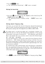
UÊ *ÀiÃÃÊ̅iÊ

 button.


—>  The “Adjusting the output levels of the channel strips” – “

LEVEL

” menu is 

activated. 


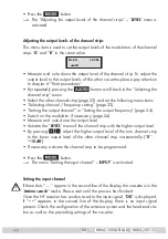
Adjusting the output levels of the channel strips


This menu item is used to set the output levels of the modulators of the channel 

strips “

A

” and “

B

” to the same value.

Bx 4A
  -3 dB

LEVEL


UÊ i>ÃÕÀiÊ>˜`ʘœÌiÊ`œÜ˜Ê̅iʜÕÌ«ÕÌʏiÛiÊœvÊ̅iÊV…>˜˜iÊÃÌÀˆ«°Ê/œÊ>`ÕÃÌÊ̅iÊ

output level to the output levels of the other cassettes please pay attention 

to chapter 6 “Final procedures”.

Ê

UÊ  ÞÊÀi«i>Ìi`ÞÊ«ÀiÃȘ}Ê̅iÊ

 button scroll back to the “Selecting the 

channel strip” menu.

Ê

UÊ -iiVÌÊ̅iʜ̅iÀÊV…>˜˜iÊÃÌÀˆ«

 (page 23) and set the following menu items:

Ê

UÊ º-iiV̈˜}ÊV…>˜˜iÊÉÊvÀiµÕi˜VÞÊÃiÌ̈˜}»Ê­«>}iÊÓή°

Ê

UÊ º-iÌ̈˜}Ê̅iʜÕÌ«ÕÌÊV…>˜˜i»ÊœÀʺ-iÌ̈˜}Ê̅iʜÕÌ«ÕÌÊvÀiµÕi˜V޻ʭ

page 24).

Ê

UÊ -܈ÌV…Êœ˜Ê̅iʓœ`Տ>̜ÀʈvʘiViÃÃ>ÀÞÊ­

page 24).

Ê

UÊ i>ÃÕÀiÊ>˜`ʘœÌiÊ`œÜ˜Ê̅iʜÕÌ«ÕÌʏiÛi°

Ê

UÊ V̈Û>ÌiÊ̅iÊ

LEVEL

” menu of the channel strip with the higher output level.

Ê

UÊ  ÞÊ«ÀiÃÈ

ng 

 adjust the higher output level of the one channel strip 

to  the  lower  output  level  of  the  other  channel  strip  incrementally  (“

0

»Ê oÊ

–10 dB

”).

Ê

UÊ vʘiViÃÃ>ÀÞÊ>V̈Û>ÌiÊ̅iÊV…>˜˜iÊÃÌÀˆ«Ê̜ÊLiÊ«Àœ}À>““i`°

Ê

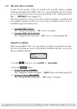
UÊ *ÀiÃÃÊ̅iÊ

 button.


—>  The menu “Setting the input channel” – 

INPUT

” is activated. 


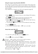
Setting the input channel


If three dots “ 

Ê»Ê>««i>Àʈ˜Ê̅iÊÃiVœ˜`ʏˆ˜iʜvÊ̅iÊ`ˆÃ«>Þ]Ê̅iÊV>ÃÃiÌÌiʈÃʈ˜Ê̅iÊ

station search

” mode. Please wait until the process has finished. 

Ê

"˜ViÊ̅iÊÊÀiViˆÛiÀʅ>ÃÊÃޘV…Àœ˜ˆÃi`Ê̜Ê̅iʈ˜«ÕÌÊÈ}˜>]ʺ

OK

” is displayed. 


If  “

–  –

»Ê >««i>ÀÃÊ ˆ˜Ê Ì…iÊ ÃiVœ˜`Ê ˆ˜iÊ œvʠ̅iÊ `ˆÃ«>Þ]ʠ̅iÀiÊ ˆÃÊ ˜œÊ ˆ˜«ÕÌʠÈ}˜>Ê

present. Check the configuration of the antenna system and the head-end sta-

tion as well as the preceding settings of the cassette.

Summary of Contents for HDMT 1000 ASI LAN

Page 1: ...SS Grundig SAT Systems GmbH Beuthener Strasse 43 D 90471 Nuremberg Phone 49 0 911 703 8877 Fax 49 0 911 703 9210 E mail info gss de Internet http www gss de HDMT 1000 ASI LAN HDMT 1001 C Head End Digital Modulator COFDM QAM ...

Page 2: ...11 3 2 EMC regulations 11 3 3 Overview of the cassette 12 3 4 Connecting the cassette 13 3 5 Retrofitting a CA module 13 4 The control panel at a glance 14 4 1 Menu items 14 4 2 Control panel 14 5 Programming 15 5 1 Preparation 15 5 2 Programming procedure 16 Channel strips A without CA module and B 16 Channel strip A with CA module 19 5 3 Programming the cassette 20 Selecting the cassette 20 Sele...

Page 3: ...ase of an incorrect input signal 32 Setting the transport stream ID and the ORGNET ID 33 Network Information Table NIT 33 Setting the network operator identification 34 Deleting a PID 35 Renaming a PID 35 Factory reset 36 Saving settings 36 5 3 1 Operation with a CA module 37 Setting the scrambling 37 Setting the PID monitoring 38 Configuring the CA module 38 Setting the station filter 39 6 Final ...

Page 4: ...Õ ÌÞÊV iVÌ ÃÊ ÀÊ À À ÌiÊ Ê UÊ LÃiÀÛiÊÌ iÊÀi iÛ ÌÊÃÌ À à ÊÀi Õ Ì ÃÊ Ê Õ i iÃÊ ÊÌ iÊ ÃÌ Ì Ê Ê iÀ Ì Ê vÊ Ìi ÊÃÞÃÌi Ã Ê UÊ iÊ ÃÌ À ÃÊ É É Ê ÊxäänÎÊ Ê É É Ê ÊÈäÇÓnÊ ÕÃÌÊ LiÊ LÃiÀÛi Ê UÊ Ê ÌÊ iÀv À Ê ÃÌ Ì Ê ÊÃiÀÛ ViÊÜ À Ê ÕÀ ÊÌ Õ iÀÃÌ À à UÊ Test the software versions of the head end station and the cassette and update them if necessary The current software versions can be found at www gss de Ê UÊ For f...

Page 5: ... Ê iÊ À ÕVÌÊvÕ v ÃÊÌ iÊ Õ i iÃÊ ÊÃÌ À ÃÊv ÀÊ Ê Li Unless otherwise noted all values are specified as typical HF input ÀiµÕi VÞÊÀ i Ê ÇÇ xÊoÊÓÓÈ x Ê Ç ÊoÊnxnÊ â Input level Ê ÈäÊ 6ÊoÊnäÊ 6 ÊÌ À Õ Ê ÕÌ ÕÌÊ Ê äÊ ÊoÊÎÊ Symbol rateÊ VV ÊÌ Ê ÊÎääÇ HF output ÀiµÕi VÞÊÀ i Ê Ó äÊ âÊoÊnÈä äÊ âÊ Channels Ê Ó ÊoÊ È Types of modulation Ê Ê Ê È ÊÎÓ ÊÈ Ê Ón ÊÓxÈ Output level Ê 96 dBµV Output impedance Ê 75 ASI i...

Page 6: ... Ê output Additionally it is equipped with an ASI input and an ASI output ASI Asynchronous Serial Interface according to EN 50083 9 The transport stream fed via the ASI socket can be inserted into the transport streams of the receiving stages via the TPS module The signal path is set in the menu items input signal path INROUTE and output signal path OUTROUTE 2 4 1 Input signal path INROUTE Menu se...

Page 7: ...Menu setting A ASI 1 A ASI 2 The transport streams of the receiving stage A TS A and of the ASI input TS ASI are split into transport stream 1 and 2 Receiving stage B is not used TS A Transport stream 1 Transport stream 2 SAT input A ASI input Receiving stage A TPS CA module TPS TS ASI 2 4 2 Output signal path OUTROUTE Menu setting ASI ASI Transport stream 1 is made available via modulator A ÊÌÀ Ã...

Page 8: ...port stream 2 2 4 3 General The cassette is equipped with two channel strips A and B The channel ÃÌÀ ÃÊV Ã ÃÌÊ vÊÌ iÊ Ì ÊÌiÀÀiÃÌÀ ÊÌÕ iÀÃ ÊÌ iÊ Ì ÊÃ Ê Ài À Ì ÊÕ ÌÃÊ and the output converter The channel strips are indicated in the head end station display with Bx A and Bx B Using an adequate CA module encoded channels can be decoded via channel strip A In addition cassette HDMT 1001 C is able to sc...

Page 9: ...s Ê Óää Ê ÊÎ È Ê Ê n und PST 19 1 2 5 Software query Control unit Ê vÊ iViÃà ÀÞ ÊÞ ÕÊV Ê VÌ Û ÌiÊÌ iÊ V Ì Ê vÊÌ iÊà vÌÜ ÀiÊÛiÀÃ Ê vÊÌ iÊ control unit manually Ê UÊ ÀiÃÃÊ ÞÊÌÜ Ê iÞÃÊ ÊÌ iÊV ÌÀ ÊÕ ÌÊ vÊÌ iÊ i i ÊÃÌ Ì ÊÃ Õ Ì i Õà ÞÊ Õ Ì ÊÌ iÊ Ã ÞÊ iÃÊ À Ê ÊÌ iÊà vÌÜ ÀiÊÛiÀà Êi ʺV 41 appears 2 6 How the TPS module works Ê vÌiÀÊ iV Ê Õ Ìi Ê Ã Ã Ê Ì iÊ i Õ Ìi Ê Ì Ê ÃÌÀi ÃÊ and the data stream fed via t...

Page 10: ...changed a new NIT must be generated Changing the NIT The transport stream contains data in the form of tables which the receiv ers evaluate and require for convenient use The TPS module can adjust the Network Information Table NIT to accommodate the new station data The NIT contains data which is required by the set top boxes connected to the cable network for the automatic search feature Changing...

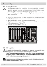
Page 11: ...bus bar Ê UÊ ÃÌi ÊÌ iÊV ÃÃiÌÌiÊÜ Ì ÊÌ iÊÃVÀiÜÃÊ1 0 1 1 66 77 66 77 66 77 66 77 66 77 66 77 66 77 66 77 66 77 66 77 66 77 66 77 5 9 567b5 5 MESSAUSGANG 20dBµV AUSGANG max 106dBµV ACHTUNG VordemKassettenwechsel unbedingt denNetzsteckerziehen CAUTION Before changingcassettesremove mainsplug UXQGLJ 6 7 6yVWePV 3 2 EMC regulations To comply with the current EMC regulations it is necessary to connect th...

Page 12: ...s made be tween the housing 19 cabinet and cable terminals 3 3 Overview of the cassette 9 8 5 4 7 6 3 2 1 1 HF input channel strip B 2 Loop through output of input 1 3 HF input channel strip A 4 Loop through output of input 3 5 LAN socket intended for additional functions 6 ASI input 7 ASI output 8 Slot for a CA module 9 D SUB socket RS 232 The operating software of the cassette can be updated via...

Page 13: ...channels via an adequate CA module Check with the distributor or manufacturer of the CA module to be used to ensure that it is suitable for descrambling several channels The hardware and software of this cassette have been thoroughly prepared and tested Any changes made by programme provider to the structures in the pro gramme data might impair or even prevent this function Ê qÊ 7 i ÊÜ À ÊÜ Ì ÊÌ i...

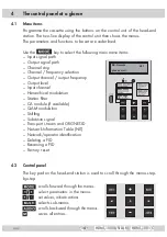
Page 14: ...ncy selection Output channel output frequency Output level Input channel Hierarchical modulation Station filter CA module if available QAM modulation Stuffing Substitute signal Transport stream and ORGNET ID Network Information Table NIT Network operator identification Deleting a PID Renaming a PID Factory reset 4 2 Control panel The key pad on the head end station is used to scroll through the me...

Page 15: ... Ê ÕÌ ÕÌÊ ÀÊÌ iÊÌiÃÌÊ ÕÌ ÕÌÊ vÊÌ iÊ i i Ê station Ê UÊ iÌÊÌ iÊ ÕÌ ÕÌÊV i ÊÉÊ ÕÌ ÕÌÊvÀiµÕi VÞÊ vÊÌ iÊcassette page 23 and adjust the TV test receiver to this channel frequency Ê UÊ Switch on the channel strip modulator if necessary page 24 For each V i ÊÃÌÀ ÊÌ iÀiÊ ÃÊ ÊÃÌ ÌÕÃÊ ÊÜ V Ê V ÌiÃÊ vÊÌ iÊV i ÊÃÌÀ Ê ÃÊ switched on Status LED Channel strip B Status LED Channel strip A UÊ ViÊÌ iÊ ÕÌ ÕÌÊ iÛi Ã...

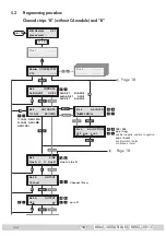
Page 16: ... V 12 COFDM TPM Box 1 Bx 1A C5 12 S3 24 TWIN SAT C07 Böx 4 C5 12 S3 24 TWIN SAT C07 Box 5 t 10 s Bx 4 A B ASI 1 INROUTE ASI 2 A ASI 1 B ASI 2 A B ASI 1 ASI 2 A ASI 1 A ASI 2 1 ASI ASI MA 2 ASI ASI MB ASI ASI A Bx 4 1 ASI OUTROUTE ASI MA Bx 4 108000 KBits ASI RATE 188 204 pos neg positiv negativ positive negative cont burst kontinuierlich burst continuous burst Bx 4 188 pos cont ASI OPTION Å Ï Å Ï ...

Page 17: ...rnen hinzufügen Removing activating stations nächster Service Programm next service station 01 10 ASI TV Programme entfernen hinzufügen Removing activating stations nächster Service Programm next service station Bx 4A 64 QAM QAM normal Å Ï Å Ï 4 256 normal inverse Bx 4A SR 6900 STUFFING 1000 7500 Bx 4A Null Packets FAILURE C D Kanalzug A mit CA Modul Channel strip A with CA module Kanalzug A ohne ...

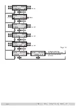
Page 18: ... Make Bx 4A PID 0x0000 DROP off Bx 4A 0xDE00 CAT ID off Å Ï Bx 4A 0x0000 0000 REMAP off Å Ï on off Å Ï on off Å Ï Å Ï on off Å Ï Å Ï off on M M M M M M M B A Å Bx 4A Defaults FACTORY Bx 4A STORE FACTORY M auf Werkseinstellung zurücksetzen und speichern reset to factory defaults and store Page 16 ...

Page 19: ...odul The information displayed is dependent on the CA module used Bx 4A 01 03 Information MENU Bx 4A TV X 04 09 X entschlüsseln descrambling 0 nicht entschlüsseln no descrambling X 0 nächster Service next service Bx 4A PID Check CA on Å Ï on off M Å Ï D Bx 4A scramble CA scramble descramble C scramble descramble Page 17 Page 17 only HDMT 1001 C ...

Page 20: ... button previous menus can be activated Ê UÊ Ü ÌV Ê ÊÌ iÊ i i ÊÃÌ Ì The display shows the software version of the head end station e g V 41 The processor reads the cassettes data approx 10 seconds BE Remote please wait V 41 t 10 s Ein On Selecting the cassette Box 4 V 12 COFDM TPM Box 1 Box 5 UÊ i iVÌÊÌ iÊcassette you want to programme e g Box 4 by repeatedly press ing the button if necessary The ...

Page 21: ...electing the output signal path OUTROUTE menu is activated Selecting the output signal path In this menu you define the signal path of the output transport streams Menu setting ASI ASI page 7 Menu setting 1 ASI ASI MA page 8 Menu setting 2 ASI ASI MB page 8 Bx 4 1 ASI OUTROUTE ASI MA UÊ 1ÃiÊÌ iÊ buttons to select the signal path wished Ê UÊ vÊÞ ÕÊ Ê ÌÊÜ ÌÊÌ Ê Ê ÊÃiÌÌ Ã Ê ÀiÃÃÊÌ iÊ button The Selec...

Page 22: ...Ê Ì Ê V iÌÃ ÊÌ i ÀÊ À ÌÞÊ ÊÌ iÊÌÞ iÊ of transmission For this setting please take the required information from the documentation technical data of the ASI component to be connected Bx 4 188 pos cont ASI OPTION UÊ ÀiÃÃÊÌ iÊ ÊLÕÌÌ ÃÊÌ ÊÃiÌÊÌ iÊÃ âiÊ vÊÌ iÊ Ì Ê V iÌÃÊ º188 or 204 bits Ê UÊ vÊÌ iÊ À ÌÞÊ vÊÌ iÊ Ì ÊÌ ÊLiÊÌÀ Ã ÌÌi Ê ÃÊÌ ÊLiÊV i Ê ÀiÃÃÊÌ i buttons to place the cursor under pos positive s...

Page 23: ...t you can only use the channel centre frequency of the existing V i Ê À Ê ÊÌ iÊÀ iÊ vÊV i ÃÊ Ó ÊoÊ È Ê vÀiµÕi VÞÊ À ÊnÊ â Ê Please note thereby that many receivers cannot receive the channel ranges Ó ÊoÊ Ê ÎäÈÊoÊ ÈÈÊ â Ê iÊ ÊV i Ê À Ê ÃÊÇÊ âÊ ÊÌ iÊÀ iÊ vÊÌ iÊ ÜiÀÊvÀiµÕi VÞÊL ÃÊ V i ÃÊ ÓÊoÊ Óä Ê iÀiv ÀiÊÌ iÊvÀiµÕi VÞÊÃiÌÌ Ê ÃÊÕÃi Ê iÀi Ê vÊ iÊÕÃiÃÊ Ì iÊiÝ ÃÌ ÊV i Ê À Ê vÊÇÊ âÊ ÊÌ iÃiÊV i ÊÀ ià ÊÌ Ã...

Page 24: ...ripÊ Ó äÊoÊnÈä äÊ â Additionally the modulator of the channel strip can be switched off or on page 24 Bx 4A 474 00 MHz OUTPUT on UÊ 1ÃiÊÌ i buttons to place the cursor under the digit to be set for the frequency display then use to set the output frequency wished Switching the modulator off or on Bx 4A C21 OUTPUT on Ê UÊ ÊÃÜ ÌV Ê vvÊÌ iÊ Õ Ì ÀÊ ViÊÌ iÊVÕÀà ÀÊÕ iÀʺon using the button and switch of...

Page 25: ...Ì ÕÌÊV i Ê Àʺ iÌÌ ÊÌ iÊ ÕÌ ÕÌÊvÀiµÕi VÞ Ê page 24 Ê UÊ Ü ÌV Ê ÊÌ iÊ Õ Ì ÀÊ vÊ iViÃà ÀÞÊ page 24 Ê UÊ i ÃÕÀiÊ Ê ÌiÊ Ü ÊÌ iÊ ÕÌ ÕÌÊ iÛi Ê UÊ VÌ Û ÌiÊÌ iÊ LEVEL menu of the channel strip with the higher output level Ê UÊ ÞÊ ÀiÃà ng adjust the higher output level of the one channel strip to the lower output level of the other channel strip incrementally 0 Ê oÊ 10 dB Ê UÊ vÊ iViÃà ÀÞÊ VÌ Û ÌiÊÌ iÊV i ...

Page 26: ...rip modulator is switched off Ê UÊ ÊÀiÌÕÀ ÊÌ ÊÌ iÊ Ê i ÕÊ ÀiÃÃÊÌ i button Ê UÊ ÀiÃÃÊÌ iÊ button The menu Setting the hierarchical modulation INPUT Priority is activated Setting the hierarchical modulation Ê Ê À iÀÊÌ Ê ÌÌ ÊÜ Ì Ê iÃÃÊv i ÊÃÌÀi Ì Ê Ê Ài ÌiÀÊÀ iÊv ÀÊLÀ V ÃÌiÀÃ Ê Ü Ì Ê 6 Êà V i ʺ iÀ ÀV V Ê Õ Ì Ê ÃÊÕÃi Ê ÊÌ ÃÊ À ViÃà ÊÃiÛiÀ Ê data streams are modulated onto a DVB T data stream using Qu...

Page 27: ... the Setting the station filter PROGRAM menu If the input signal path A ASI 1 B ASI 2 or A ASI 1 A ASI 2 is se lected the channel strips can be programmed one after the other The default setting for the station filter is off In this menu you define the sta tions received to be transmitted If stations are activated the output data rate increases If the station filter is switched off factory default...

Page 28: ...er PROGRAM off 01 04 ASI TV Å Ï on off Bx 4B Filter PROGRAM on Ê UÊ Press the button Ê p Ê ÊÃÌ Ì ÃÊvÀ ÊÌ iÊV i ÊÃÌÀ ÊÜ ÊLiÊÀi Ê ÊÌ i Ê Ã Þi ÊÜ Ì Ê name and station type Pressing the button all stations can be activated or deactivated Ê p Ê vÊ ÊÃÌ Ì Ê ÃÊv Õ ÊÌ iÊv Ü ÊiÀÀ ÀÊ iÃÃ iÊÜ Ê i ÀÊ ÊÌ iÊ Ã play FILTER no Service Ê Ê ÊÌ ÃÊV Ãi ÊV iV ÊÌ iÊV v ÕÀ Ì Ê vÊÌ iÊ Ìi ÊÃÞÃÌi Ê Ê i i Ê ÃÌ Ì Ê ÃÊÜi Ê ÃÊÌ...

Page 29: ...on provider are required If a service number e g 131 appears instead of TV or RA ÊÌ ÃÊ indicates that an unnamed station or an undefined data stream is being received UÊ 1ÃiÊÌ i LÕÌÌ ÃÊÌ ÊV ÊÕ ÊÌ iÊÃÌ Ì ÃÊ ÊÃiµÕi Ì Ê À iÀ ÊÌ i ÊÕÃiÊ to activate indicated by or to deactivate them indicated by Ê U Press the button Ê UÊ iÌÊÌ iÊÃÌ Ì Êv ÌiÀÃÊ vÊV i ÊÃÌÀ ʺB and ASI in the same way as chan nel strip A T...

Page 30: ... QAM menu is activated when the channel strips A without a CA module in stalled and B are programmed Programming the channel strip A with a CA module installed the set tings for the CA module are activated page 37 Setting the QAM modulation Ê ÊÌ ÃÊ i Õ ÊÞ ÕÊV ÊÃiÌÊÌ iÊ Ê Õ Ì Ê Ê ÛiÀÌÊÌ iÊÕÃiÀÊà Bx 4A 64 QAM QAM normal Ê UÊ Use to set the QAM modulation 4 Êoʺ256 Ê p Ê ÀÊ iÀÊ Ê Õ Ì ÊÌ iÊ ÕÌ ÕÌÊÃÞ L...

Page 31: ... Ê iÊÛ ÕiÊv ÕVÌÕ Ìià Êà ViÊÌ iÊ Ì ÊÀ ÌiÃÊ vÊ Û Õ ÊÃÌ Ì ÃÊ ÀiÊ Þ cally modified by the broadcasters Number 2 is not displayed in the channel strips A or B at the set tings OUTROUTE 1 ASI ASI MA or 2 ASI ASI MB Êv ÀÊ the symbol rate of the ASI input signal cannot be measured The ASI input signal therefore must be built in such a way so that the output symbol rate Number 1 is not exceeded The symbol ...

Page 32: ... a substitute signal in the case of an incorrect input signal FAILURE menu is activated Setting a substitute signal in the case of an incorrect input signal You use this menu to set whether a QAM signal filled with Null Packets Ê a QAM signal filled with null packets and self made tables Tables or a Single Carrier signal should be provided as an output signal whenever an incorrect input signal occ...

Page 33: ...iÊ button place the cursor under off and switch on the trans mitter identification using the buttons By pressing the button you return to the hexadecimal number setting Ê UÊ ÀiÃÃÊÌ iÊ button The Network Information Table NIT menu is activated Network Information Table NIT Bx 4A off NIT Make Ê UÊ ÊÃÜ ÌV Ê Ê É vvÊ ºon off press the buttons Ê UÊ ÀiÃÃÊÌ iÊ button to activate NIT Make Ê VÌ ÛiÊo ÊV ÃÃiÌ...

Page 34: ...ional Access Table Idi Ì v V Ì Êv ÀÊiÝ iÊ vÊÌ iÊÛ Ã Û Ã ÊÌÀ Ã ponder Eutelsat 8 West Bx 4A 0xDE00 CAT ID off CAT is not to be changed Ê UÊ ÀiÃÃÊÌ iÊ button The Deleting a PID DROP menu is activated page 35 Changing the CAT The network operator e g requires that you set the operator ID of the visAvi sion transponder to 2 Ê UÊ Use the buttons to position the cursor under the digit to be set Ê UÊ 1Ãi...

Page 35: ... REMAP menu is activated Renaming a PID In this menu you can allocate a new address to a PID retaining the complete data content Bx 4A 0x0000 0000 REMAP off Ê UÊ 1ÃiÊÌ iÊ buttons to place the cursor under the respective digit of the hexadecimal number of the PID to be changed 0x0000 and set the hexadecimal number using Ê UÊ 1ÃiÊÌ iÊ buttons to place the cursor under the respective digit of the hex...

Page 36: ...e 20 By pressing the ÊLÕÌÌ ÊÞ ÕÊÜ ÊLiÊÀiÌÕÀ i ÊÌ ÊÌ iÊ i ÕÊ Ìi Ê Selecting the channel strip via B without saving the factory defaults page 23 If necessary set channel strip B Saving settings Ê UÊ ÀiÃÃÊÌ iÊ button Returning to Selecting the cassette menu via connection A page 20 The settings are saved Ê p Ê vÊvÕ VÌ ÃÊ vÊÌ iÊ Ê Õ iÊ ÀiÊ VÌ Û Ìi ÊÌ i ÀÊÃÌ ÌÕÃÊ ÃÊÃ Ü Ê ÊÌ iÊ second line of the menu M...

Page 37: ...ns and un scrambled regional broadcasters Cassette HDMT 1001 C The Setting the encoding CA menu is activated Cassette HDMT 1000 ASI LAN The Setting the PID monitoring CA menu is activated page 38 Setting the scrambling With cassette HDMT 1001 C it is possible to scramble unscrambled channels 9 ÕÊV ÊÃiÌÊÜ iÌ iÀÊÞ ÕÊÜ ÌÊÌ Ê iÃVÀ L iÊÃVÀ L i ÊV i Ã Ê ÀÊÌ ÊÃVÀ ble unscrambled channels Bx 4A scramble C...

Page 38: ...you are using For this rea Ã Ê i ÃiÊÀiviÀÊÌ ÊÌ iÊ iÀ Ì Ê Õ Ê vÊÞ ÕÀÊ ÀÌ VÕ ÀÊ Ê Õ i Ê iÊ relevant information is shown in the display of the head end station This may appear as a fixed display or as scrolling text according to display capabilities Bx 4A Menu CA Edit Bx 4A 01 03 Information MENU Bx 4A TV X 04 09 Å Ï M Bx 4A TV X 04 09 Å By pressing the button you can skip the Configuring the CA mod...

Page 39: ...can cancel the settings in the menu of the CA module and are returned to the Configuring the CA module CA menu Ê UÊ ÀiÃÃÊÌ iÊ button The Setting the station filter Edit menu is activated Setting the station filter Ê ÊÌ ÃÊ i ÕÊÞ ÕÊÃi iVÌÊÌ iÊÃÌ Ì ÃÊÜ Ã i ÊvÀ ÊÌ iÊÃVÀ L i Ê Ì ÊÃÌÀi Ê which are to be descrambled Bx 4A Menu CA Edit Bx 4A 01 03 Information MENU Bx 4A TV X 04 09 Å Ï M Bx 4A 01 03 Inform...

Page 40: ...ll up the stations in sequential order which are to LiÊ iÃVÀ L i ÊÌ i ÊÕÃi to descramble X or not to descramble them 0 Save changes and activate the station filter Ê UÊ ÀiÃÃÊÌ iÊ button The filter is activated The display shows the Configuring the CA mod ule CA menu Bx 4A Menu CA Edit Ê UÊ ÀiÃÃÊÌ iÊ button The Setting the QAM modulation QAM menu is activated page 30 ...

Page 41: ... Ê Êappropriate open ended spanner Ê UÊ i ÃÕÀiÊÌ iÊ ÕÌ ÕÌÊ iÛi ÃÊ vÊÌ iÊ Ì iÀÊV ÃÃiÌÌiÃÊ ÊÌÕ iÊÌ i ÊÌ Ê ÊÕ v À Ê output level using the appropriate level controls or software dependent on the head end station used Please regard the assembly instructions of the respective head end station In order to prevent interference within the head end station and the cable ÃÞÃÌi ÊÌ iÊ ÕÌ ÕÌÊ iÛi ÃÊ vÊÌ iÊ Ì Ê...

Page 42: ... ÌÌi vÀiµÕi â Channel centre frequency Q â S 30 378 00 S 31 386 00 S 32 394 00 S 33 402 00 Kanal Channel ÌÌi vÀiµÕi â Channel centre frequency Q â S 34 410 00 S 35 418 00 S 36 426 00 S 37 434 00 Kanal Channel ÌÌi vÀiµÕi â Channel centre frequency Q â S 38 442 00 S 39 450 00 S 40 458 00 S 41 466 00 C 21 474 00 C 22 482 00 C 23 490 00 C 24 498 00 C 25 506 00 C 26 514 00 C 27 522 00 C 28 530 00 C 29 ...

Page 43: ...Alterations reserved Technical data E O E GSS GmbH V12 07012010 Service Phone 49 0 911 703 2221 Fax 49 0 911 703 2326 Email service gss de ...

Reviews: