


67
Fan and Heater
SMART BOARD
Fan and Heater
"SMART BOARD" is the name of the new printed
circuit board in your heater. The purpose of this new
board is to simplify the procedure for checking out
the heater in case of a malfunction. "SMART
BOARD" uses a series of lights to check for power at
various locations in the heater circuit. Lights that are
lit have power going to those components or loca-
tions, lights that are not lit indicate a lack of power at
the terminal or location. During the operation of the
heater, some check points should have power and
some should not have power. The lights are num-
bered (1 through 7, A and B). Following is informa-
tion to help identify which lights should be lit, what
problem may exist and explain the operation of the
SMART BOARD.
Standard Heaters ( not HI-LO fire):
When standard heater units are first turned on the and
the purge time is completed (10 seconds), auto-check
lights #1 through #6, A and B should be lit. When
flame is established A and B will drop out. Light #7
is used only on HI-LO fire units and does not function
on standard units.
HI-LO Fire Heater
On HI-LO fire units, all of the light sequences are the
same as on standard units, except light #7 will be lit
on high flame, and goes out when switching to low
flame.
When the plenum chamber reaches the preset tem-
perature of the humidistat-thermostat, lights 1 and 2
will be lit all other lights will be out. Once the flame
goes out, light A will be lit and after the purge delay,
lights 3 and 4 will be lit also. When the plenum
chamber cools to the point of requiring more heat,
lights 5 and 6 will be lit again. The cycle should
continue until the unit is shut off.
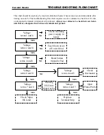
The information below lists the light number(s) and
what they indicate. Follow the chart down to the
appropriate condition the unit is in, then read across
to the explanation. Once the problem has been
identified, you can proceed to fix the problem.
NOTE: Remove power and inspect all electrical
connections before any other troubleshooting. If any
connections are loose, tighten them and retry opera-
tion.
If a problem should occur, by
following the instructions, the
reason a heater does not maintain
flame should be easily deter-
mined. As with any trouble-shooting, do not put
ANYTHING inside the electrical box when the unit
has power supplied to it. Be sure power is discon-
nected at the breaker before servicing.
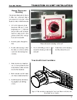
If the heater unit does not operate properly, remove
the electrical box cover and look at the Auto-Check
board. By looking at the lights on the board, the
problem should be easily identified. With the on-
off switch on, determine which lights are lit and
which are not.
Summary of Contents for PNEG-377
Page 1: ...Fan And Heater PNEG 377 Service Manual 2 0 0 0 EDITION...
Page 2: ......
Page 6: ...6 Fan and Heater...
Page 7: ...7 Fan and Heater 2000 VANE AXIAL FANS...
Page 9: ...9 Fan and Heater TEST STATION...
Page 14: ...14 Fan And Heater FAN WIRING AND SCHEMATIC Wiring 240 Volt 1 Phase 15 HP Schematic...
Page 17: ...17 Fan And Heater 2000 CENTRIFUGAL FAN SERVICE GUIDE...
Page 24: ...24 Fan and Heater 2000 Gas Heater Service Guide...
Page 49: ...49 Fan and Heater WIRING DIAGRAM...
Page 56: ...56 Fan and Heater WIRING SCHEMATIC...
Page 57: ...57 Fan and Heater STANDARD HEATER WIRING...
Page 58: ...58 Fan and Heater STANDARD HEATER SCHEMATIC...
Page 61: ...61 Fan and Heater NOTES Notes...
Page 62: ...62 Fan And Heater 1996 1994 Gas Heaters...
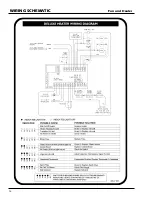
Page 63: ...63 Fan And Heater DELUXE HEATER WIRING...
Page 64: ...64 Fan And Heater DELUXE HEATER SCHEMATIC...
Page 65: ...65 Fan And Heater DELUXE HEATER SCHEMATIC 1993 1995 Heaters...
Page 70: ...70 Fan and Heater 1991 1993 GAS HEATERS...
Page 72: ...72 Fan And Heater WIRING SCHEMATIC 1991 1992 Heaters...
Page 73: ...73 Fan and Heater 1990 GAS HEATERS...
Page 76: ...76 Fan and Heater PRE 1990 GAS HEATERS...
Page 77: ...77 Fan and Heater HEATER WIRING DIAGRAM...
Page 78: ...78 Fan and Heater HEATER SCHEMATIC Vane Axial LP Heater...
Page 79: ...79 Fan and Heater HEATER SCHEMATIC Vane Axial Vapor Heater...
Page 80: ...80 Fan and Heater HEATER SCHEMATIC Downwind LP Heater...
Page 81: ...81 Fan and Heater HEATER SCHEMATIC Downwind Vapor Heater...
Page 82: ...82 Fan and Heater HEATER SCHEMATIC Lo Fire Downwind Heater...
Page 83: ...83 Fan and Heater MISCELLANEOUS INFORMATION...
Page 93: ...93 Fan and Heater FENWAL SERIES 05 14 Figure 2 Figure 3...
Page 97: ...97 Fan And Heater...
Page 98: ...1004 E Illinois St Assumption IL 62510 Phone 217 226 4421 Fax 217 226 4498 February 2000...


