


35
Fan and Heater
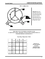
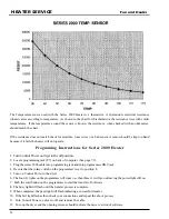
HEATER INSTALLATION
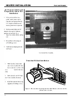
1. Be sure fan unit is installed and
wired to meet local codes. Be
sure equipment is well grounded
(see page 10).
2. A separate neutral is required
for 120 volt heater circuit in 220
volt 1PH and 3PH fan units. For
460 volt fan units a separate 120
volt power supply or transformer
is required.
3. Run 5-wire black cord from
heater unit to fan unit and se-
cure to fan.
4. Orange and red wires should be
connected in series with coil in
fan. When contacts in heater be-
tween these wires open fan
Wiring
Heater Unit
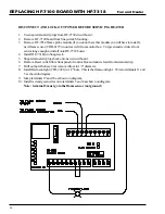
4. Third heater unit may also be added to system.
If adding third unit, run connections to master
unit #1 and connect them in parallel with sec
ondary heater unit.
2. Run (2) 20 gauge (minimum) wires from sec-
ondary heater unit (slave) to heater unit #1
1. Secondary heater unit runs as a slave of heater
unit #1 and requires no plenum temperature
sensor.
Figure 3: Secondary heater wiring diagram.
Figure 2: Wiring diagram for the fan and heater unit.
SECONDARY HEATER UNIT
shuts down. Recommended wiring is shown in Figure 2.
5. Black and white wires should be connected to a fused 120V
power supply as shown. Green wire should be connected to
ground in fan. Heater should have power, even with fan off.
(master).
3. Connect wires as shown in Figure 3.
Summary of Contents for PNEG-377
Page 1: ...Fan And Heater PNEG 377 Service Manual 2 0 0 0 EDITION...
Page 2: ......
Page 6: ...6 Fan and Heater...
Page 7: ...7 Fan and Heater 2000 VANE AXIAL FANS...
Page 9: ...9 Fan and Heater TEST STATION...
Page 14: ...14 Fan And Heater FAN WIRING AND SCHEMATIC Wiring 240 Volt 1 Phase 15 HP Schematic...
Page 17: ...17 Fan And Heater 2000 CENTRIFUGAL FAN SERVICE GUIDE...
Page 24: ...24 Fan and Heater 2000 Gas Heater Service Guide...
Page 49: ...49 Fan and Heater WIRING DIAGRAM...
Page 56: ...56 Fan and Heater WIRING SCHEMATIC...
Page 57: ...57 Fan and Heater STANDARD HEATER WIRING...
Page 58: ...58 Fan and Heater STANDARD HEATER SCHEMATIC...
Page 61: ...61 Fan and Heater NOTES Notes...
Page 62: ...62 Fan And Heater 1996 1994 Gas Heaters...
Page 63: ...63 Fan And Heater DELUXE HEATER WIRING...
Page 64: ...64 Fan And Heater DELUXE HEATER SCHEMATIC...
Page 65: ...65 Fan And Heater DELUXE HEATER SCHEMATIC 1993 1995 Heaters...
Page 70: ...70 Fan and Heater 1991 1993 GAS HEATERS...
Page 72: ...72 Fan And Heater WIRING SCHEMATIC 1991 1992 Heaters...
Page 73: ...73 Fan and Heater 1990 GAS HEATERS...
Page 76: ...76 Fan and Heater PRE 1990 GAS HEATERS...
Page 77: ...77 Fan and Heater HEATER WIRING DIAGRAM...
Page 78: ...78 Fan and Heater HEATER SCHEMATIC Vane Axial LP Heater...
Page 79: ...79 Fan and Heater HEATER SCHEMATIC Vane Axial Vapor Heater...
Page 80: ...80 Fan and Heater HEATER SCHEMATIC Downwind LP Heater...
Page 81: ...81 Fan and Heater HEATER SCHEMATIC Downwind Vapor Heater...
Page 82: ...82 Fan and Heater HEATER SCHEMATIC Lo Fire Downwind Heater...
Page 83: ...83 Fan and Heater MISCELLANEOUS INFORMATION...
Page 93: ...93 Fan and Heater FENWAL SERIES 05 14 Figure 2 Figure 3...
Page 97: ...97 Fan And Heater...
Page 98: ...1004 E Illinois St Assumption IL 62510 Phone 217 226 4421 Fax 217 226 4498 February 2000...


