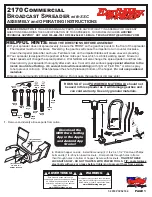
background image

10

PARTS LIST

ITEM #

1
2
3
4
5
6
7
8
9

10
11
12
13
14
15
16
17
18
19
20
21
22
23
24
25
26
27
29
30
31
32
33
34
35
36
37

*Denotes items included in gear box assembly.
All parts are standard except for items 1, 2, 10, 36 & 41.
(See description for applications).

PART #

002-1105-2
002-1088-0
017-1534-1

SPD-2154

TFC-0054

FH-6563

SPD-2151
SPD-2068
SPD-2069
SPD-2070
SPD-2008
SPD-2149
SPD-2062
SPD-2061
SPD-2004
SPD-2063
SPD-2003
SPD-2005
SPD-2171
SPD-2006
SPD-2064

*

S-277

SPD-2109

S-1054

S-456

S-6606
S-3611
S-6076

S-845

S-6606
S-6078
S-6079
S-6077
S-7621

*

SPD-2108

TFH-2104

FH-7001

QUANTITY

1
1
1
1
1
1
1
1
1
1
3
3
2
1
1
1
3
1
1
2
1
1

12

*

4
4

15
34

6
6
5
2
1
2
4
1

1
1

DESCRIPTION

1 HP 1-Phase C-Face Motor (special)
1 HP 3-Phase C-Face Motor (special)
Pinion Gear
MI Gear Box With 56C Adapter (069-1304-0)
3/4" Seal-Tite Elbow-CSA
3/4" Seal-Tite CSA Approved
3/4" 45 DEG Seal-Tite Fitting
Capacitor Box
Capacitor Box Lid
Capacitor Clip
Hanger Extension
Hanger Bracket
Gear Box Mounting Bracket
Spreader Cone
Upper Back-up Plate
Spreader Blade
Spreader Diverter
Lower Back-up Plate
Drive Shaft Weldment
Damper
Blade Extension
Set Screw
5/16"-18 x 1.1/4" Hex Capscrew, grade 5
Special Gearbox Lubricant
3/8" Lockwasher
3/8"-16 Hex Nut
5/16" x 3/4" Hex HD Bolt (serrated)
5/16"-18 Hex Nut
5/16"-18 x 3/4" Carriage Bolt
5/16" Flatwasher
5/16"-18 x 3/4" Hex HD Bolt (serrated)
5/16"-18 x 1/4" Set Screw
1/4" x 1" Roll Pin
U-Bolt 3/8"-16 x 1"W x 2.1/4" Lg.
10-32 x 3/4" Self Tap Screw
3/8" Eyebolt
1 HP Spreader Blade Replacement Kit
EC1216C06 Capacitor (1 Phase)
OC3020F12 Capacitor (1 Phase)

FFD-200-1 (1 PH MOTOR) & FFD-200-3 (3 PH MOTOR)

Summary of Contents for FFD-200-1

Page 1: ...1 Scattergrain Grain Spreader Installation Operating Instructions Owner s Manual MANUAL PNEG 267 MODEL FFD 200 1 MODEL FFD 200 3 PNEG 267...

Page 2: ...2...

Page 3: ...ware List For FFD 200 1 FFD 200 3 8 Super Spread Parts List 10 Super Spread Parts Assembly 11 Super Spread Installation 12 Single Phase Dual Voltage Wiring Diagram 13 Three Phase Dual Voltage Wiring D...

Page 4: ...MODIFICATIONS TO THE PRODUCT NOT SPECIFICALLY COVERED BY THE CONTENTS OF THIS MANUAL WILL NULLIFY ANY PRODUCT WAR RANTY THAT MIGHT HAVE BEEN OTHERWISE AVAILABLE THE FOREGOING WARRANTY SHALL NOT COVER...

Page 5: ...ous injury or death SAFETY GUIDELINES DANGER indicates an imminently hazardous situation which if not avoided will result in death or serious injury This is the safety alert symbol It is used to alert...

Page 6: ...al concern of the GSI Group Inc GSI is your safety and the safety of others associated with grain handling equipment This manual is written to help you under stand safe operating procedures and some o...

Page 7: ...is supplied to your unit Safety decals should be read and understood by all people in the grain handling area The bottom right de cal should be present on the inside bin door cover of the two ring do...

Page 8: ...Bracket 5 16 18 x 1 1 4 N F T Bolt grade 5 5 16 Lockwasher 5 16 18 Hex Nut 5 16 Flatwasher 5 16 18 x 1 4 Set screw 1 4 x 1 Roll Pin 3 8 Eyebolt Danger Decal 1 4 Set Screw 1 4 x 1 Roll Pin 1 4 Set Scre...

Page 9: ...ets All GSI bins with stan dard peak roof cap have a hatch collar diameter 31 1 2 Loosely mount each hanger extension to a hanger bracket using the ap propriate slots with two 5 16 18 x 1 1 4 bolts tw...

Page 10: ...special 1 HP 3 Phase C Face Motor special Pinion Gear MI Gear Box With 56C Adapter 069 1304 0 3 4 Seal Tite Elbow CSA 3 4 Seal Tite CSA Approved 3 4 45 DEG Seal Tite Fitting Capacitor Box Capacitor B...

Page 11: ...SEMBLY WARNING Automatic Reset Overload Protection NOTE Tighten set screws against flat on motor shaft Special Gearbox Lubricant Locating holes must be aligned for proper operation Not required for sm...

Page 12: ...kwise as viewed from above the unit If the three phase unit turns clockwise the rotation can be changed This may be done by interchanging any two of the three power wire con nections The rotation cann...

Page 13: ...and the extra wire on the capacitor go to L1 4 goes to L2 and 2 and J tie together E from the motor goes to E on the capacitor O from the motor goes to O on the capacitor For 230 volts 1 goes to L1 2...

Page 14: ...efore servicing all power to the unit must be disconnected and locked out to avoid a possible reset restart and serious injury Before connecting and applying power rotate the spreader blade by hand to...

Page 15: ...er and fill rate Figure 8 2 Spreader diverters are used to increase or decrease grain flow resistance over spreader blade With the diverters straight Fig ure 9 the grain will travel fur ther Angled gr...

Page 16: ...lts and pivot dampers to nearly closed position SMALL BIN 24 DIA AND LESS OPERATION PROCEDURE Increase loosen U bolts and pivot the blade single diverter side upward Increase center filling loosen bol...

Page 17: ...ration If problem con tinues check power supply for volt age and check blade of unit for free dom of rotation If motor pinion requires removal for any reason it must be properly installed and located...

Page 18: ...reader never allow grain to flow into spreader at an angle or off center Trouble Large doughnut shaped ring caused by grain hitting high on bin wall Grain is high in center of bin small doughnut Grain...

Page 19: ...19...

Page 20: ...20 1004 E Illinois St Assumption IL 62510 Phone 217 226 4421 Toll Free Fax 888 741 3004 Rev June 26 2003 G R A I N C O N D I T I O N I N G S Y S T E M S...

Reviews: